What's new
  • Happy Birthday ICMag! Been 20 years since Gypsy Nirvana created the forum! We are celebrating with a 4/20 Giveaway and by launching a new Patreon tier called "420club". You can read more here.
  • Important notice: ICMag's T.O.U. has been updated. Please review it here. For your convenience, it is also available in the main forum menu, under 'Quick Links"!

ebb & Grow/ Multiflow controller construction

BlindDate

Active member
Veteran
If you think that pin 3 is the switching pin on the timer then use it regardless of what the drawing I saw says. I'm confused now. But you have certainly used it enough to know by now what with the hair dryer and all. Please tell me which pin is switching in sync with the timer settings? Is it 3 or 4?
 
Last edited:
yeah its pin 3

but the funny thing is the relays are clicking on and off when the timer 15 min increments tabs are in the up position which means the timer is off??????? Why are they clicking then?

im confused
 
yeah i just tested it again and when i trun the timer dial to the ON (Tabs down) position and flick the power the relays do nothing.

When the timer is in the off (Tabs UP) position anf i flick the power the relays coils flick up and down making noise

is that the way its supposed to be ?
 
actually i think i have made a mistake the tabs that are up i think mean timer on, not off!!!! Fuck

And when they are down its means off???? i think that might be right. i have been doing the opposite


i have just lifted all the timer tabs into the up positions and when i hit the power the relay clicks like bird .... fantastic.

When all the timer tabs are down the relay will not click at all and thus no power to the relay.

i actually have been mixed up the whole time
 
Last edited:
I have just been testing the relays throught the timer and all is go ahead and working fine.

Have been sitting here for a few hours and trying blind dates float to relay configurations with no success just can seem to power the relays through the timer and float switch.

is there a way to test to see if my floats are working ????

direct way i mean because the relays ar not the issue now
 

BlindDate

Active member
Veteran
Earl.........Pins 3 & 4 will decide which way the timer clicks on and off. Meaning whether the timer tabs are UP or Down.

If you have the power connection on pin 3 and it turns on with timer tabs UP then put the power connection on pin 4 and it will turn on with timer tabs DOWN. Understand?

In light of this info, I'll stand that your power connection IS pin 4 and the thing is meant to turn on with the tabs down. Just like the timer schematic shows.
 
Last edited:

imnotcrazy

There is ALWAYS meaning to my madness ®
Veteran
Usually timers work when you pull the tabs UP. I believe your problem is in the fact that the timer DOES NOT wire directly to the relay coils. The timer somehow routes through the float switches, so when the float moves (depending on position) they make/break the relay. The timer only initiates this whole process, therefore the floats MUST be wired IN SERIES with the relay/timer circuit.

My opinion, the controller bucket uses Two Float Switches per Relay, one to turn on the relay and the other to trun off. I feel one Float MUST be setup Normally open and the other Normally closed inorder to accmplish this (OR it is done using the NO/NC contacts of the Relay). I'll try to draw a diagram for you in Microsoft Paint to give you a better Idea what I mean..

EDIT: Yeah check this pic from Kryptos completed relay setup:
233Controler_10-19-04_010-med.jpg


Notice how there is only ONE Black lead on the coil connections, I believe this is the Initiation lead coming off of the timer. ALL of the other connections, whether coil or NO/NC contacts is coming from the RED float switch leads.
 
Last edited:

imnotcrazy

There is ALWAYS meaning to my madness ®
Veteran
Relay Positions (I believe)

From Krypto's thread / Your Relays

1/1 2/4
3/5 4/8
5/9 6/12

and the coil connections

7/13 8/14


BTW, the above is following the layout of this picture you posted:
18409relay_diagram.jpg


You have to check, but I believe this will correct your problem. I'm going off of memory on what the Omron relay layout is, by drawing a picture because I can't find a good diagram and they label the RadioShack versions differently than the Actual Omron relays.
 
Last edited:
hay blind date i just tested the hair dryer on pin 4 and with the tabs reversed but the hair dryer will not turn on at all during the UP or DOWN phase!!!!

so what does that mean ??? No power at all on pin 4.
 
imnotcrazy said:
Usually timers work when you pull the tabs UP. I believe your problem is in the fact that the timer DOES NOT wire directly to the relay coils. The timer somehow routes through the float switches, so when the float moves (depending on position) they make/break the relay. The timer only initiates this whole process, therefore the floats MUST be wired IN SERIES with the relay/timer circuit.

My opinion, the controller bucket uses Two Float Switches per Relay, one to turn on the relay and the other to trun off. I feel one Float MUST be setup Normally open and the other Normally closed inorder to accmplish this (OR it is done using the NO/NC contacts of the Relay). I'll try to draw a diagram for you in Microsoft Paint to give you a better Idea what I mean..

EDIT: Yeah check this pic from Kryptos completed relay setup:
233Controler_10-19-04_010-med.jpg


Notice how there is only ONE Black lead on the coil connections, I believe this is the Initiation lead coming off of the timer. ALL of the other connections, whether coil or NO/NC contacts is coming from the RED float switch leads.


yeah mate i can see that, thanks for pointing that out mate but i think there is 2 positives from the 2 power plug outlets that power the pump.

yeah i think thats right the bacl power plug fill and drain outlets are going to pin 5 as per kyptos thread.

thankls for helping me guys
 
Last edited:

imnotcrazy

There is ALWAYS meaning to my madness ®
Veteran
Let me check Krypto's thread again and I'll get back to ya on that one....
 
AS PER KYYPTOS THREAD

Take the black/positive lead from the Drain Outlet and attach the female connect to

Relay A #4


Take the positive lead from the Fill outlet and attach it to

Relay B #4 .
 

imnotcrazy

There is ALWAYS meaning to my madness ®
Veteran
233Controler_10-19-04_053-med.jpg


As you can see from this pic direct from Kryptonite's thread, the Hot leg is jumpered yes, but both connections go to the timer. One is the timer connection to power the clock, the other to the Common connection for the relay portion of the timer.

The Power comes off the NO/NC portion of the timer (dependant on timer mode of operation), the power to the outlets is determined by the relays through the operation of the floats...
 

imnotcrazy

There is ALWAYS meaning to my madness ®
Veteran
Also, forgot to mention, there are 4 floats. Two on the bottom, two on the top. One top/bottom set controls each relay.. I am certain of this.
 

imnotcrazy

There is ALWAYS meaning to my madness ®
Veteran
You DO have the jumpers assembled in the same fashion as Kryptonite did, yes?

If so, refer to my post containing the relay reference numbers, wire it up using my cross reference between the Kryptonite relay numbers and double check the operation... I'm fairly certain we are damn close to figuring this out.

The only thing I ask of you, one we get this working is to post pictures of the backs of the relays. Also LABEL the float jumpers, ie: Top Left, Top Right, Bottom Left, Bottom Right.

That way, EVERONE will have a good reference to work off of, because obviously the relay numbers won't always match
 
Last edited:
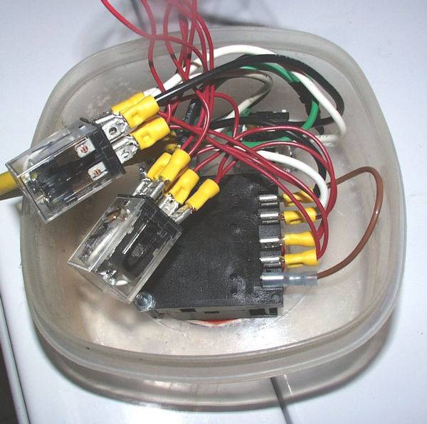
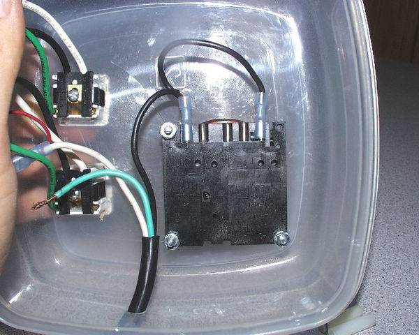
i am getting power to the relay through the timer and the timer is clearly working so know i guess i need to make sure all wiring is correct and that the connection are all correct for this to work.


is there a way to run just 2 float switches, 1 at the top and 1 at the bottom just to make this less complicated wiring wise and see if we can get it to work that way.

kudos to you guys for taking thet ime to help me
 
Last edited:

imnotcrazy

There is ALWAYS meaning to my madness ®
Veteran
imnotcrazy said:
Relay Positions (I believe)

From Krypto's thread / Your Relays

1/1 2/4
3/5 4/8
5/9 6/12

and the coil connections

7/13 8/14


BTW, the above is following the layout of this picture you posted:
18409relay_diagram.jpg


You have to check, but I believe this will correct your problem. I'm going off of memory on what the Omron relay layout is, by drawing a picture because I can't find a good diagram and they label the RadioShack versions differently than the Actual Omron relays.


Use this to cross reference to Kryptonite's thread to wire it back up. Check operation.. I think I have it sorted for you bro..

Edit: Let me clarify, in the quote, the numbers work like this:

The layout of the numbers cooresponds to the relay layout from the picture you posted. First number = Krypto's relay number / Second number = cooresponding pin for your relays with your relay numbers. Try this out...
 
Last edited:

Latest posts

Latest posts

Top