
You are using an out of date browser. It may not display this or other websites correctly.
You should upgrade or use an alternative browser.
You should upgrade or use an alternative browser.
ebb & Grow/ Multiflow controller construction
- Thread starter MyNameIsEarl
- Start date
MyNameIsEarl
Member
hahahahaha i thought so
will be back soon
will be back soon
MyNameIsEarl
Member
LIFT OFF
There is power to the timer, just got out of the shower and drying my hair as we speak ahahhahahah

so i guess that makes it either the relays or the floaty switches ????
Also when i plugged it in it woul;dnt work then i realised i didnt have the positive jumper connected to pin 5. So i plugged in pin 5 and BAM was drying my hair.

Last edited:
MyNameIsEarl
Member
im starting to think its really the relays!!!
or it could be the floats s they were purchased off ebay from China but i did check them up against a car battery and they kicked so i guess they work.
Only other option is the wire I used for the jumpers for the float switches. I purchased a 1mm/16 guage blue sheath copper wire from my local radio shack. I think this is not the problem because really im just extending the switches and only carrying small current through the switches to the relays.
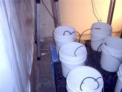
How can i power these switches like in the photo's below??? I just want to rule out that its the float switches, if it is then it can only be the relays!!!
I like this process of elimination!!!
Those pictures here with the light on the battery were off the guys internet shop i didnt take these photos.


or it could be the floats s they were purchased off ebay from China but i did check them up against a car battery and they kicked so i guess they work.
Only other option is the wire I used for the jumpers for the float switches. I purchased a 1mm/16 guage blue sheath copper wire from my local radio shack. I think this is not the problem because really im just extending the switches and only carrying small current through the switches to the relays.
How can i power these switches like in the photo's below??? I just want to rule out that its the float switches, if it is then it can only be the relays!!!
I like this process of elimination!!!
Those pictures here with the light on the battery were off the guys internet shop i didnt take these photos.


Last edited:
OK...Process of elimination, next:
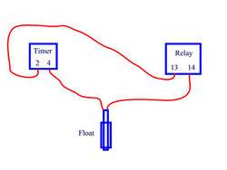
Lets see if the relays are working. Run power directly from the timer pins 2 & 4 to pins 13 & 14 on the relay and see if the relay clicks. Test one relay at a time and remove all the other connections first.
NEXT:
Test the floats (one by one) in circuit. As you lift and drop the float the relay should click. Remember that you still need power on pins 2 & 5.

Last edited:

MyNameIsEarl
Member
Will do mate just rigging the floats up now.
Yeah i do appreciate the help!!!!!
Yeah i do appreciate the help!!!!!
MyNameIsEarl
Member
ok just tested the relays as per blind dates instructions.
ran pin 2 timer into position 13
ran pin 4 timer into position 14
tried vice versa but nothing seems to resemeble a clicking sound. I had my ear up to it and nothing at all.
i tried the rest of the positions on the relays but no clcking or anything resembling life.!!!!
where to go from here


ran pin 2 timer into position 13
ran pin 4 timer into position 14
tried vice versa but nothing seems to resemeble a clicking sound. I had my ear up to it and nothing at all.
i tried the rest of the positions on the relays but no clcking or anything resembling life.!!!!
where to go from here


Last edited:
This may be a dumb question, but, I'll assume that the timer is ON when you are testing.
Pins 13 & 14 are the coil contacts. They activate the relay.
It appears that your relays are not working. Are you sure that those relays are 220 Volt coils? Give me a close up of the markings on the relay.
Pins 13 & 14 are the coil contacts. They activate the relay.
It appears that your relays are not working. Are you sure that those relays are 220 Volt coils? Give me a close up of the markings on the relay.
Last edited:
MyNameIsEarl
Member
sure are, on the cylindrical yellow object inside the relay it says AC 220-240V
just double checked timer and yes timer is on and working but just seems to be be the relays i guess i cant check the floats until i trouble shoot the relays.
Here are my relays I purchased
http://www.rsaustralia.com/
ITEM NUMBER :2508796181
I am going to get this bastard to work if its the last thing i do. I like multiflow but you cant get them in Australia anywhere.


Last edited:
You don't have a cord you casn use to test the relays do you?
Terminals 13 and 14 are DEFINITLY the coil terminations (the terminals that are oriented up/down on the bottom of the relay)
You must ensure the timer is on and applying the proper voltage for the relay to operate.
Terminals 13 and 14 are DEFINITLY the coil terminations (the terminals that are oriented up/down on the bottom of the relay)
You must ensure the timer is on and applying the proper voltage for the relay to operate.
MyNameIsEarl
Member
ok,
on the back of the relay it has the pin layout as per picture below
it says :
RH2B-U = model number
AC 220-240V
50/60 HZ

on the other side of the relays it says:
CSA Rating
RES
10A 240 VAC
10A 30VDC
GEN USE
7.5A 120VAC
7A 240VAC
7.5A 30VDC
1/6 HP 120VAC
1/3 HP 240VAC
Made in China
that is everything written on the relays

Last edited:
#s 13 and 14 are CERTAINLY the coil connections
hook up wires to each and use an outlet to test the relays, then get back to us
hook up wires to each and use an outlet to test the relays, then get back to us
MyNameIsEarl
Member
I do have a spare cord can you give me a rough diagram on how to wire it???
cheers
i think i know but i dont want to zap myself
would the positive wire go to pin 14 and negative to pin 14???
cheers
i think i know but i dont want to zap myself
would the positive wire go to pin 14 and negative to pin 14???
Last edited:
MyNameIsEarl
Member
yessssssssssssssss
They work !!!! i just connected the positive wire to pin 13 and the negative wire to 14 that were connected to the timer and the relays coils were flicking up and down.
i wonder why they are not working when connected with the timer.
i am going to test them through the timer aswell and ill get back
They work !!!! i just connected the positive wire to pin 13 and the negative wire to 14 that were connected to the timer and the relays coils were flicking up and down.
i wonder why they are not working when connected with the timer.
i am going to test them through the timer aswell and ill get back
MyNameIsEarl
Member
ok i just stumbled upon the right combo the relays are now working with the timer but its not pin 4!!!!! its connected to pin 3 and the relays are flicking
yippe kar yay motherfuckers its about time.
timer pin 2 jumper connected to relay pin 14
timer pin 3 connected to relay pin 13
yippe kar yay motherfuckers its about time.
timer pin 2 jumper connected to relay pin 14
timer pin 3 connected to relay pin 13
MyNameIsEarl
Member
ok trying to test he float switches are per blind dates instructions but nothing is happening.
i may try another float switch just to make sure
i may try another float switch just to make sure

