What's new

ebb & Grow/ Multiflow controller construction

imnotcrazy

There is ALWAYS meaning to my madness ®
Veteran
Ok, you need to wire the top switch Normally closed in SERIES with the relay that shuts down the fill pump. That will turn off the system when it reaches the fill level. You didn't mistakenly purchase NO floats did you?

EDIT: Found your problem brother, you needed a SPDT timer relay

Refer to Krypto's post here: http://www.icmag.com/ic/showpost.php?p=76718&postcount=2
 
Last edited:

BlindDate

Active member
Veteran
Not if you want to ensure that your room doesnt flood/ the pumps always flood to the proper height EVERY TIME
How can the room flood? Remember...You are pumping THROUGH a mechanical float valve in the controller bucket.

Edit: If they can run dry, why do the instructions that come with mag-drive pumps ALWAYS say DO NOT RUN DRY???

Don't use a mag drive pump. Use a direct drive pond pump like the Beckett pumps sold at Home Depot. They are excellent pumps.

Look....If you want to build a contraption, then go ahead, but it reminds me of the old board game "mousetrap" or a cartoon where a hundred things happen before the final result.
So I will say it again:
All you are doing is pumping water from the reservoir to the controller bucket and back. All you need is 2 pumps on timers that alternate.
 
Last edited:
imnotcrazy said:
Ok, you need to wire the top switch Normally closed in SERIES with the relay that shuts down the fill pump. That will turn off the system when it reaches the fill level. You didn't mistakenly purchase NO floats did you?

EDIT: Found your problem brother, you needed a SPDT timer relay

Refer to Krypto's post here: http://www.icmag.com/ic/showpost.php?p=76718&postcount=2

what do you mean i did get the right one didnt i ??

here is the specs for my timer


Electrical > Electrical Components


Grasslin Wattmaster NHP flush panel mount timecloc

Grasslin Wattmaster NHP 24hr timeclock.
Flush mounts into airswitch boxes, chlorinators, heaters, etc
Complete with clip on clear cover
Contacts rated at 250V, 50Hz, 16A (resistive load) 6.3mm spade terminals x 5 (normally open and closed contacts)
Relays should be used in conjunction with timeclock where pump rating exceeds 1.5hp
72mm x 72mm, requires a 67mm x 67mm hole
 
imnotcrazy said:
Ok, you need to wire the top switch Normally closed in SERIES with the relay that shuts down the fill pump. That will turn off the system when it reaches the fill level. You didn't mistakenly purchase NO floats did you?

EDIT: Found your problem brother, you needed a SPDT timer relay

Refer to Krypto's post here: http://www.icmag.com/ic/showpost.php?p=76718&postcount=2

also what are no floats ???

my pictures are float switches the normal kind i guess
 
i just looked up the email from the supplier asking for more info and this is what the supplier sent......

The Grasslin timer is a 5 terminal time clock - 2 terminals are the motor,
the other 3 are common, normally open, and normally closed which switch with
the timer settings - this is the only configuration on normal timeclocks
although some have only normally open contacts. Ie the Grasslin is SPDT

Regards,
 

BlindDate

Active member
Veteran
NO means Normally Open. It is referring to the circuit. Those floats can be set Normally Open or Normally Closed. To reverse them, remove the clip, slide off the float and turn it around. Then reinstall the clip.
 
BlindDate said:
NO means Normally Open. It is referring to the circuit. Those floats can be set Normally Open or Normally Closed. To reverse them, remove the clip, slide off the float and turn it around. Then reinstall the clip.


thanks for the tip blind date! :joint:

what set up are you running? :chin:
 
Last edited:

BlindDate

Active member
Veteran
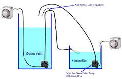
OK...This is my last attempt to persuade you guys to Keep it Simple. This is the setup I'm babbling about. Same thing, far less complexity. At least tell my why you do not like it.

 
ok here are the float switches i purchased


As you see i i have removed the C Clip and turned the float around so that it is reflective of PICTURE 2.

Im going to take my float switches off and see if i can see the magnetic rod inside them to double check and make sure they are the same

Still no good though, no power to the pump??? :badday:

here are the specs for the float switches​
Material specification :

Float ball: P.P
Float body:p.p
Tempe Rating :-10----+105 ℃
Max Contact Rating :70W
Max Switching voltage :220VAc
Max Switching Current :0.7A
Wire Lengh : 450mm


Here is also what the guys says where i purchased the float switches:....


install : This float switch is easily installed at the top of a tank by means of a threaded union and washer incorporated in the body of the switch. .

how to working :The switch consists of a floating magnet and a miniature electromagnetic switch contained within the tube.

The electric circuit is normally open when the tank is full: Float up = switch open, no electrical flow.

As the water level lowers, the float sinks and the circuit closes. Float down = switch closed, active current flow.

Installing the float 180 degrees will reverse the electrical conditions to:

float up = switch closed. Float down = switch open.


Last edited:
BlindDate said:
OK...This is my last attempt to persuade you guys to Keep it Simple. This is the setup I'm babbling about. Same thing, far less complexity. At least tell my why you do not like it.


ok what happens when the controller gets full and the toilet float closes but the reservoirs timer and pump are still running wont the float blow if the pump is still running???

thats a big question i think!
 
Last edited:
just changed all the float switches around to the magent at the end of ther "C" Clip on the float but still not working.

Im sure i has to be the relays positions because the timer and all the wiring was double checked and noting is wrong. All connections are firmly fit and the female connectors are solidly connected

im stumped!!
 

Budweiser13

Active member
Earl I built this system all I can say is That I purchased the exact relays and timer that are in krypto's thread. I had to read the thread a couple of times to get it figured out. Blind Date I know you are trying to help but are beating a dead horse why change something that already works. With your setup you still need timers and ya still need float valves so on and so forth. The krypto controller works bitchin when wired up correctly. Keep up the good fight Earl.......... :wave:
 
hahahaha yeah the fight is a hard one.

im really thinking of chucking it all in and selling off the parts and just purchasing one from the USA shipped to Australia.

Ive already spent over $200 and have nothing that works to show for it!!!

i mean ive got the dough$$$$ to get it so why not?

oh well im going to play with the relays and try some different configurations and see how that works!

you never know i might stumble upon the right configuration
 
Last edited:

BlindDate

Active member
Veteran
ok what happens when the controller gets full and the toilet float closes but the reservoirs timer and pump are still running wont the float blow if the pump is still running???

Yeah...Because aquarium pumps put out so much pressure that they will blow your tubes apart like a bomb. And then the shrapnel will kill everyone in the room! Is this question a joke?? Were talking about a fricking aquarium pump. They put out about 4-5 psi at best. Float valves are made for house pressure (about 150 psi). And even still, remember the anti-siphon vent? BTW..That float valve is not a toilet one.


C-mon guys, try to do better than that.


Last edited:

BlindDate

Active member
Veteran
Blind Date I know you are trying to help but are beating a dead horse why change something that already works. With your setup you still need timers and ya still need float valves so on and so forth.

But only 1 float!

Yes..This is true, but what you do not need is the ability to assemble an electrical circuit. For some people like myself putting together the Krypto system is ridiculously easy. I work with relays and such all the time and have designed some sophisticated automatic systems. Then there are people like Earl, who do not have the background for such a thing. Also, I am of the belief that simpler is better and more reliable (KISS).
 
Last edited:

BlindDate

Active member
Veteran
Earl....If you ever get that thing working don't forget to install the anti-siphon vent. If not, your pump will turn off, but the nutes will keep flowing. Krypto used a small 90 deg barb and said that it was important, yet never went on to tell why. I'm sure that many omitted and learned the hard way.
 
Last edited:
BlindDate said:
Earl....If you ever get that thing working don't forget to install the anti-siphon vent. If not, your pump will turn off, but the nutes will keep flowing. Krypto used a small 90 deg barb and said that it was important, yet never went on to tell why. I'm sure that many omitted and learned the hard way.

yeah no worries thanks for that.

Seems like im not going to be able to get it working. The wiring is correct but i can even get power to the fill outlet. So basically in stumped on the first thing and thats getting power to the fill outlet.

Im going to try some configs tonight just for testing and see ow it works out.
 

BlindDate

Active member
Veteran
This may be a dumb question, but did you wire power to the relay? I'm not talking about the relay coil, but the center contact. Also, when you lift and drop the float is the relay clicking?
 
BlindDate said:
This may be a dumb question, but did you wire power to the relay? I'm not talking about the relay coil, but the center contact. Also, when you lift and drop the float is the relay clicking?

not sure what you mean i know the negative/nutural wire from the power cord is connected to the relay through the jumpers and the positive leads from the fill / drains out lets connect to each relay A and B.

Maybe you might be able to help me out as pretty much no fuck all about relays and how they work :pointlaug

cheers
 
Last edited:

BlindDate

Active member
Veteran
Take clear close-up pictures of all your wiring and I'll figure out what is wrong. Also, answer my other question. When the timer is ON and you lift the floats, are the relays moving (clicking)??
 
Last edited:

Latest posts

Latest posts

Top