
Yes I know, no timer
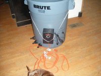
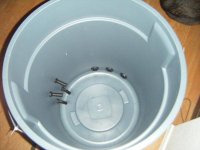
It has been a while and like I already said, I had several of these running. 9 to be exact. No timer just a set of switches,relay and a pump to pump back to a rez. I also built this controller but used a different timer and added a relay to make the timer work.
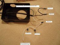
When the timer turns on and off it sends power to one set of relays since it is Double throw. Understand? You do understand the timer in this DIY is a DP and sends power to one of the relays at all times based on its on or off position. That way the flood outlet is active at the right time, and the drain outlet is active at the right time
^^^^ That is more FYI so you have an understanding of how this works
Since you want power 24/7 the wires that should attach to the timer, should go to a 120 outlet instead(or your local voltage)
Replace TIMER in your instructions with 120 outlet.
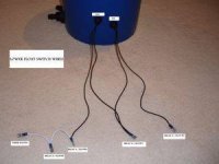
AGAIN, take that black and white wire that should attach to the timer, put a MALE plug with the metal prongs on them, and stick it into an outlet
So instead of the relay being activated at certain times by the timer, the relay is always active. The pump wont run, but the relay will be ready 24/7 and will activate the outlet when the switches raise
Sorry if I am not clear, do not know how to make myself any clearer
It has been a while and like I already said, I had several of these running. 9 to be exact. No timer just a set of switches,relay and a pump to pump back to a rez. I also built this controller but used a different timer and added a relay to make the timer work.
When the timer turns on and off it sends power to one set of relays since it is Double throw. Understand? You do understand the timer in this DIY is a DP and sends power to one of the relays at all times based on its on or off position. That way the flood outlet is active at the right time, and the drain outlet is active at the right time
^^^^ That is more FYI so you have an understanding of how this works
Since you want power 24/7 the wires that should attach to the timer, should go to a 120 outlet instead(or your local voltage)
Replace TIMER in your instructions with 120 outlet.
AGAIN, take that black and white wire that should attach to the timer, put a MALE plug with the metal prongs on them, and stick it into an outlet
So instead of the relay being activated at certain times by the timer, the relay is always active. The pump wont run, but the relay will be ready 24/7 and will activate the outlet when the switches raise
Sorry if I am not clear, do not know how to make myself any clearer
")


