
-
Happy Birthday ICMag! Been 20 years since Gypsy Nirvana created the forum! We are celebrating with a 4/20 Giveaway and by launching a new Patreon tier called "420club". You can read more here.
-
Important notice: ICMag's T.O.U. has been updated. Please review it here. For your convenience, it is also available in the main forum menu, under 'Quick Links"!
You are using an out of date browser. It may not display this or other websites correctly.
You should upgrade or use an alternative browser.
You should upgrade or use an alternative browser.
Ogre's DIY Ebb & Grow / Multi-Flow Controller Tutorial
- Thread starter OgreSeeker
- Start date

DIY Ebb and Grow Controller
DIY Ebb and Grow Controller
Hello all, new member here. I wanted to share my version of Ogre's (and Krypto's) controller.
I basically used the same set of parts as Ogre did, but I connected the controller timer and relays to the bucket via a 10' lead and molex connectors. I wanted to be able to keep the controller outside the room so I could easily access the timer, and so I could wash the bucket easily.
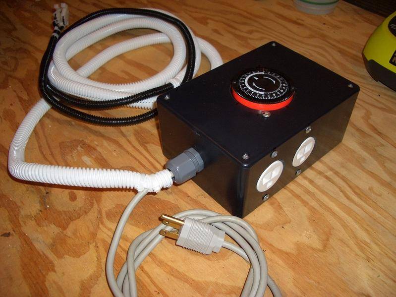
For the bucket, I used the horizontal floats but I just used the 3/4" connector and bushings instead of the bulkheads... works fine. 5 gallon bucket. Everything is connected with 3/4" tubing, and Ive used garden hose fittings at key junctions for easy disconnection.

The pots are 4 gallon buckets that I ordered online... shipping and handling was about $5 a bucket total, so not too bad.
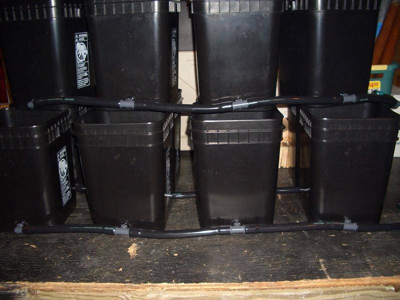
The reservoir is a 55 Gal foodservice barrel.

I have two ViaAqua 306 pumps that manage to fill the buckets (w/o hydroton) in about 10 minutes and drains in 15 minutes, so with the hydroton in the pots it will fill and drain faster.
Much thanks to Ogre and others before him for this DIY! It was fun to build and I look forward to using it (soon!). Check it out in action in my Grow Journal.
DIY Ebb and Grow Controller
Hello all, new member here. I wanted to share my version of Ogre's (and Krypto's) controller.
I basically used the same set of parts as Ogre did, but I connected the controller timer and relays to the bucket via a 10' lead and molex connectors. I wanted to be able to keep the controller outside the room so I could easily access the timer, and so I could wash the bucket easily.
For the bucket, I used the horizontal floats but I just used the 3/4" connector and bushings instead of the bulkheads... works fine. 5 gallon bucket. Everything is connected with 3/4" tubing, and Ive used garden hose fittings at key junctions for easy disconnection.
The pots are 4 gallon buckets that I ordered online... shipping and handling was about $5 a bucket total, so not too bad.
The reservoir is a 55 Gal foodservice barrel.
I have two ViaAqua 306 pumps that manage to fill the buckets (w/o hydroton) in about 10 minutes and drains in 15 minutes, so with the hydroton in the pots it will fill and drain faster.
Much thanks to Ogre and others before him for this DIY! It was fun to build and I look forward to using it (soon!). Check it out in action in my Grow Journal.
Attachments


all hooked up and in the testing stage using lamps and I've found that my floats have effect on the state of the lamps.
When I i plug the power cord into the wall, one lamp turns on (depending on state of the timer). When I rotate the timer to change states, the other lamp turns on and the first lamp turns off. During either stage, toggling the floats has no effect. Always on, always off. I'm quadruple checked my wiring and it is correct. I've re-crimped all leads as well.
complete disclosure. when I was initially hooking it up, I had the terminals on the relays backwards...the drawing on the front threw me for a loop. Is it possible that I fried my float sensors? Is there an easy way to test?
I'm using all the same parts listed in Ogre's instructions...
DISCLAIMER: Not sure which sensors the OP states to use, or what everyone else is using.
In my experience, I did fry some sensors. In one of the DIY's, was a link to Chicago Sensor http://www.chicagosensor.com/Miniature_Horizontal_Mount_Float_Switches.html
I used FLT231. If you read the spec sheets, its rated at 100VDC. But we are running 120VAC through them.
I wired up 1 controller and 8 more setups using these switches and the radio shack relay. Once in a while, I had a switch go bad. It really didnt seem like a big deal about the 120AC because it was so little amperage but I am not an electrical engineer.
The switch is a very simple device. If you have a multimeter, set it for ohms or continuity (sp?) and when you open and close the switch, it should beep/shut off or go from 0 to infinity.
After rereading your post, there is no way to reverse the switch.
leave both switches down in the bottom, turn your timer off. That should equate to your buckets draining, and water pumping back to the res. now lift the bottom float up, then the top float up. That should trigger the lamp/pump to come on
Turn the timer on, and leave the switches on the top down. That should equate to your buckets filling and your res pump filling the bucket. With the switches down, the pump/lamp should be on. Now lift the bottom switch, then the top switch. That should turn the lamp/pump off.
Remember both switches have to be activated, thats the whole point of this.
It took me a while to understand this whole procedure but after wiring up 9 of them, it was 2nd nature
Not sure what you reversed, but its possible you blew the relay
Budweiser13
Active member
Great STUFF !!! Would this controller work for a flood table?
No its not designed for a flood table its for buckets...
DISCLAIMER: Not sure which sensors the OP states to use, or what everyone else is using.
In my experience, I did fry some sensors. In one of the DIY's, was a link to Chicago Sensor http://www.chicagosensor.com/Miniature_Horizontal_Mount_Float_Switches.html
I used FLT231. If you read the spec sheets, its rated at 100VDC. But we are running 120VAC through them.
I wired up 1 controller and 8 more setups using these switches and the radio shack relay. Once in a while, I had a switch go bad. It really didnt seem like a big deal about the 120AC because it was so little amperage but I am not an electrical engineer.
The switch is a very simple device. If you have a multimeter, set it for ohms or continuity (sp?) and when you open and close the switch, it should beep/shut off or go from 0 to infinity.
After rereading your post, there is no way to reverse the switch.
leave both switches down in the bottom, turn your timer off. That should equate to your buckets draining, and water pumping back to the res. now lift the bottom float up, then the top float up. That should trigger the lamp/pump to come on
Turn the timer on, and leave the switches on the top down. That should equate to your buckets filling and your res pump filling the bucket. With the switches down, the pump/lamp should be on. Now lift the bottom switch, then the top switch. That should turn the lamp/pump off.
Remember both switches have to be activated, thats the whole point of this.
It took me a while to understand this whole procedure but after wiring up 9 of them, it was 2nd nature
Not sure what you reversed, but its possible you blew the relay
ty. had bad sensors, alls well after replacing those.
SKUNK420
Member
yes if the table was on the ground and the top of the table was level with the control bucket so that way you do not over flow the table. You do not want the table lower then the float switches. I know some people going like wtf?? why would you want to use it on a table. One reason I can think of is that you already own a E&F set up but the strain you are growing gets too tall and you need more vertical height. So what do you do? Go buy a new high dollar E&F bucket set? Hell no, just go plug the drain holes on that table, drop it to the ground and make yourself the bucket controller and get growing. Plus you can move your plants around the tray a little more easily until you put up a trellis.Great STUFF !!! Would this controller work for a flood table?
I had control bucket and used it to catch the run off water from a drain to waste coco grow. Worked great for dumping water automatically. I would never say go make or buy a C.B. for just that but if you already own one then it can have multiple uses if you put your mind to it.
cyberhippy
New member
hi all, can some1 please list all the parts needed to make this controler in uk spec (220v/240v)please please please,really need to make it and make it work proper, HELP help HELP any1
superultramega
Member
here's a wiring digram

dtfsux- If you're wiring it through a relay you should only be running 12V or 24V through the switches. I can't think of how you would wire it without the DPDT in the relay actually.
dtfsux- If you're wiring it through a relay you should only be running 12V or 24V through the switches. I can't think of how you would wire it without the DPDT in the relay actually.
superultramega
Member
Looks like they changed their design in light of this thread. The new version only has one timer and is almost identical to the construction of the controller in this thread.hi all, can some1 please list all the parts needed to make this controler in uk spec (220v/240v)please please please,really need to make it and make it work proper, HELP help HELP any1
Good price for the components too.
http://www.aquahub.com/store/product39.html
here's a wiring digram
dtfsux- If you're wiring it through a relay you should only be running 12V or 24V through the switches. I can't think of how you would wire it without the DPDT in the relay actually.
The original DIY does NOT use an alternate power supply, and uses 120. You CAN get float switches that will run 120 off Ebay, but they come from China and take a while to receive.
Not sure what you mean about the relays. I used the same relays as the OP
superultramega
Member
So you used a 120V coil relay? ah, got it. (missed that in the OP, was reading both the aquahub instructions and this thread)
Seems you've already figured it out, but adding a transformer and a 12 or 24V coil relay will let you run the float switches low voltage.
I think I'm going to build one of these. I was going to buy one but I can't get it for a week and I need it Sunday to not lose any productivity days. I'll post the results.
Lizard Fish
Active member
I was hoping someone could help me out with a slight modification to this controller bucket.I want my controller bucket just to be a drain bucket. No timer, and no high level high switches. I run trays that are on the ground and drip into them, and just use the controller bucket to empty the trays. I purchased all the supplies i need to make this and thought i could figure out how to bypass the timer, but i am stumped. I would be super stoked if someone could point me in the right direction...
I was hoping someone could help me out with a slight modification to this controller bucket.I want my controller bucket just to be a drain bucket. No timer, and no high level high switches. I run trays that are on the ground and drip into them, and just use the controller bucket to empty the trays. I purchased all the supplies i need to make this and thought i could figure out how to bypass the timer, but i am stumped. I would be super stoked if someone could point me in the right direction...
it can be done, I have done it before.
It has been a while and I dont have it anymore to look at.
Wire this up the same as the instructions but only using the lower switches. You can place them anywhere you want, just wire them up like the directions state.
There should be instructions on wiring the timer to the relay. use a constant 120V source for this instead. That way the bucket will drain 24/7 when the switches activate
I know it can be done because I ran several buckets doing what you are doing. I just cant remember how. I think you just have to swap the timer wiring for a constant power source
Lizard Fish
Active member
Yeah i put it all together, minus the connections to the timer. What confuses me is the black power cord wire is supposed to only connect to the timer. Where should i attach that to? The white power cord wire, attaches to the relay, the timer and the drain receptacle. I just left out the timer connection for the white wire.
Yeah i put it all together, minus the connections to the timer. What confuses me is the black power cord wire is supposed to only connect to the timer. Where should i attach that to? The white power cord wire, attaches to the relay, the timer and the drain receptacle. I just left out the timer connection for the white wire.
take the loose black wire and the white wire to the timer and put a plug on it and plug it into an outlet.
All the whites are together because they are the neutral and it is common.
The black is hot and is what is getting switched
I am 99% sure that will do what you want.
Lizard Fish
Active member
The problem is i am not using a timer, no need for one for how i use the controller bucket.
take the loose black wire and the white wire to the timer and put a plug on it and plug it into an outlet.
All the whites are together because they are the neutral and it is common.
The black is hot and is what is getting switched
I am 99% sure that will do what you want.

