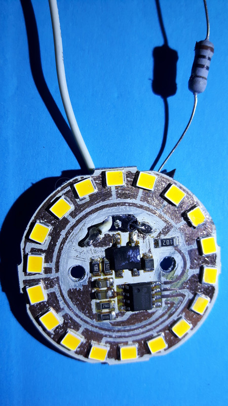
I started zap proofing my bulbs after I electrocuted myself about 14 times. I’m a slow learner. Those leads or w/e that stick out from the circuit board will zap the shit out of you lol.

-
Happy Birthday ICMag! Been 20 years since Gypsy Nirvana created the forum! We are celebrating with a 4/20 Giveaway and by launching a new Patreon tier called "420club". You can read more here.
-
Important notice: ICMag's T.O.U. has been updated. Please review it here. For your convenience, it is also available in the main forum menu, under 'Quick Links"!
You are using an out of date browser. It may not display this or other websites correctly.
You should upgrade or use an alternative browser.
You should upgrade or use an alternative browser.
Off the shelf retail store screw-in LED and CFL bulb comparisons
- Thread starter blynx
- Start date
PCBuds
Well-known member
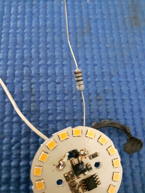
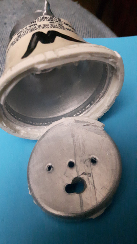
I don't know if you cut away that white "ceramic" looking stuff but I don't think you should.
That looks like a low-resistance high watt resistor. That ceramic stuff is a heat sink.
Try putting just a dab of silicone on the exposed metal and allow the heat sink to breathe.
Covering them up completely seals in the heat.
That looks like a low-resistance high watt resistor. That ceramic stuff is a heat sink.
Try putting just a dab of silicone on the exposed metal and allow the heat sink to breathe.
Covering them up completely seals in the heat.
Legalcdn
Well-known member
I hope that works nicely for you. I may be over killing with 306w for 2ft x 4ft but it seems to work nice. I try to keep the distance about 4” some colas end up an inch or two closer or further. Manifold? Like trellises? Modular trellis?
Search for mainlining vs manifold..should be 1st or 2nd search results.. Mainlining is good for seeds..manifolding for clones.. Coco for cannabis has a good article there too. Great for diy led Canopy training.
StillOvergrowin
Member
I think you may have some good points there. ( although I would tend to think of ceramic more as an insulator than a heat sink)I don't know if you cut away that white "ceramic" looking stuff but I don't think you should.
That looks like a low-resistance high watt resistor. That ceramic stuff is a heat sink.
Try putting just a dab of silicone on the exposed metal and allow the heat sink to breathe.
Covering them up completely seals in the heat.
View Image
As precise as the manufacturing is on the LED boards, it seems odd that they'd just leave random bits of point metal sticking out.
I originally thought the prongs on mine might be mini heat sinks.
Not sure if it would make sense to be both a power lead and a heat sink at the same time.
Interesting quandary. May need to call their tech support and just ask...
StillOvergrowin
Member
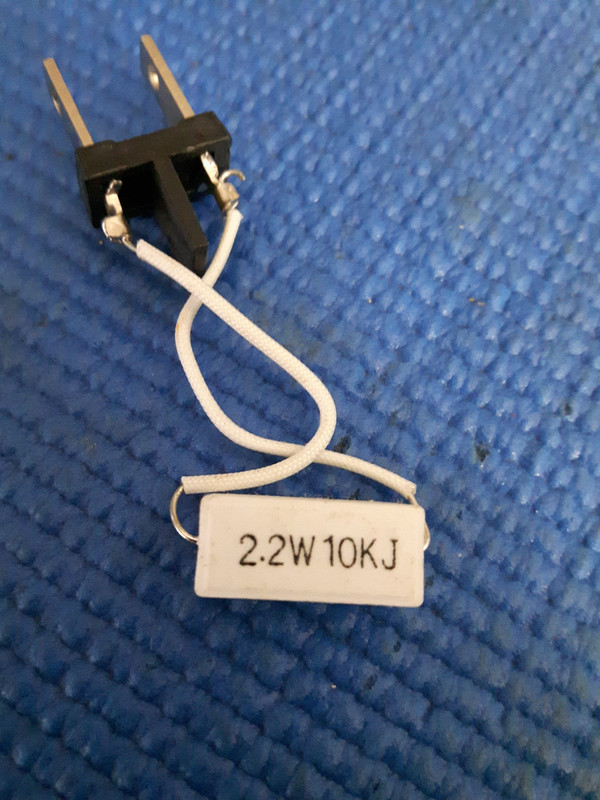
My Walmart 10 W bulbs have them too but they are in line on the wire feeding to the circuit board.
It's really low ohms (color code says 10 ohms but they measure less than 1 ohm.)
It's only a 10 W bulb so they used a regular shaped and sized resistor.
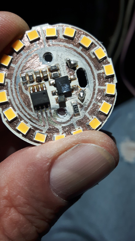
https://postimg.cc/Yhzvs90NView Image
Just curious- approximately how old are those bulbs? Any idea?
Yours looks different than the ones I posted.
And can you show the back of the board?
PCBuds
Well-known member
.. ( although I would tend to think of ceramic more as an insulator than a heat sink).
The ceramic absorbs heat and then radiates it to its surfaces.
A piece of resistive wire may get red hot.
As precise as the manufacturing is on the LED boards, it seems odd that they'd just leave random bits of point metal sticking out.
I originally thought the prongs on mine might be mini heat sinks...
They could be test points so the factory can test each PCB (and all the LED segments) before they're fully assembled.
PCBuds
Well-known member
Just curious- approximately how old are those bulbs? Any idea?
Yours looks different than the ones I posted.
They're all different.
Every company, every wattage, every year.
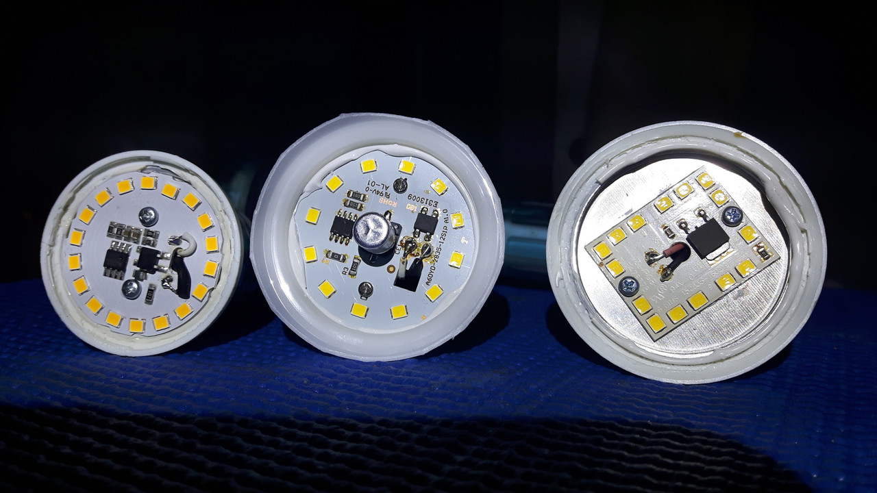
And can you show the back of the board?
Just the heat sink.
All the connections are made on the other side.
StillOvergrowin
Member
The ceramic absorbs heat and then radiates it to its surfaces.
OK, I can see how that would work...similar to radiant heat coming from cement or rock I suppose. Just doesn't seem terribly efficient.
...
They could be test points so the factory can test each PCB (and all the LED segments) before they're fully assembled.
Hmmm...good point. Oddly enough I did notice the prongs on my bulbs weren't all a matching/uniform length. Everything else on them seems really precise.
PCBuds
Well-known member
"OK, I can see how that would work...similar to radiant heat coming from cement or rock I suppose. Just doesn't seem terribly efficient"
No Shit!!
It's fricken stupid!!
scrogmonster's resistor says 94 V.

And so does mine.
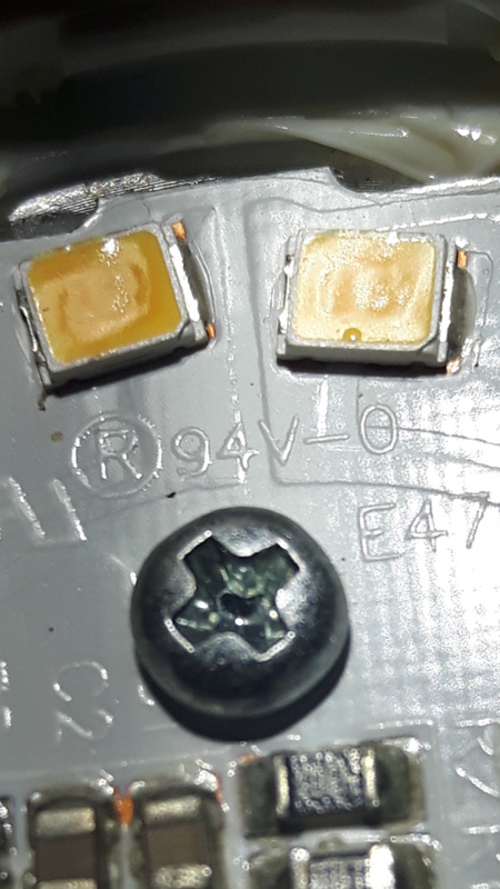
They're using a resistor to drop the voltage to 94 V and wasting all the difference as heat.
Why the hell can't they design a circuit that runs off 120 V and just add in more LED segments to get the voltage drop they need.
No Shit!!
It's fricken stupid!!
scrogmonster's resistor says 94 V.
And so does mine.
They're using a resistor to drop the voltage to 94 V and wasting all the difference as heat.
Why the hell can't they design a circuit that runs off 120 V and just add in more LED segments to get the voltage drop they need.
PCBuds
Well-known member
Oooooo.
They need a fancy-ass control circuit that controls the voltage and current to make sure that it's at it's optimum.
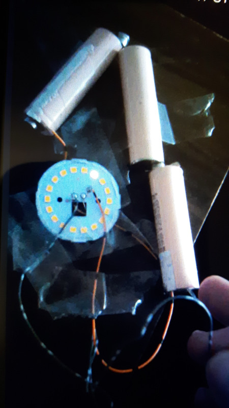
I'm going to build my own damn "driver"...
Straight LED segments driven by DC.
I've already started.
I was a few years ago when I managed to get a single LED segment to light up with DC.
It took three lithium cells, so around 12 V.
I figured the only way to find out the real voltage on each segment was to measure it while it was running.
That turned out to be difficult because the light was beaming me in my face and it was hard to put the probes in there and measure the voltage.
So I taped off of all the segments except the one I was measuring.
I should have maybe put tape on the segment I was trying to measure so I could see but I didn't think of that at the time.
7.28 volts DC per segment.
I'm building a 120 V full-wave bridge rectifier circuit with voltage regulation. (4 diodes and a capacitor).

I need to check the output voltage of my circuit. It'll be a bit less than 120 V due to inefficiencies in the diodes and capacitor.
(waste dissipated as heat).
120÷7.28= ~ 16.5 segments.
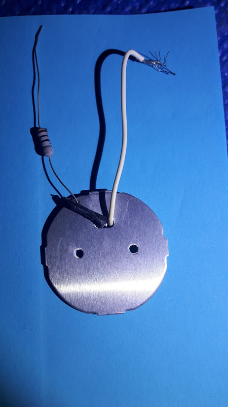
I just need to build a few simple parts.
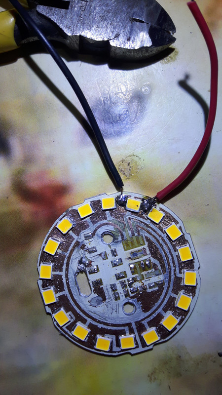
I scraped off the paint or whatever to bear the copper runs so I can solder to them.
I'll be back at it tomorrow.
I need to toke more and think.
They need a fancy-ass control circuit that controls the voltage and current to make sure that it's at it's optimum.
I'm going to build my own damn "driver"...
Straight LED segments driven by DC.
I've already started.
I was a few years ago when I managed to get a single LED segment to light up with DC.
It took three lithium cells, so around 12 V.
I figured the only way to find out the real voltage on each segment was to measure it while it was running.
That turned out to be difficult because the light was beaming me in my face and it was hard to put the probes in there and measure the voltage.
So I taped off of all the segments except the one I was measuring.
I should have maybe put tape on the segment I was trying to measure so I could see but I didn't think of that at the time.
7.28 volts DC per segment.
I'm building a 120 V full-wave bridge rectifier circuit with voltage regulation. (4 diodes and a capacitor).
I need to check the output voltage of my circuit. It'll be a bit less than 120 V due to inefficiencies in the diodes and capacitor.
(waste dissipated as heat).
120÷7.28= ~ 16.5 segments.
I just need to build a few simple parts.
I scraped off the paint or whatever to bear the copper runs so I can solder to them.
I'll be back at it tomorrow.
I need to toke more and think.
Whoever thought Marijuana was a gateway drug... well.... they were right.
I can clearly see it is a gateway drug to: carpentry, cabinetry, arduino automation, electronics, ventilation, hydroponics and indoor horticulture.
It wont be long till they start having "Build your own growbox" courses at your local Home Depot.
Marijuana - the drug of choice for DIY enthusiasts.
I can clearly see it is a gateway drug to: carpentry, cabinetry, arduino automation, electronics, ventilation, hydroponics and indoor horticulture.
It wont be long till they start having "Build your own growbox" courses at your local Home Depot.
Marijuana - the drug of choice for DIY enthusiasts.

Hookahhead
Active member
There are SILs that have the driver on a separate board than the LEDs, these would probably be easier for you to work with than worrying about soldering directly to the LED channel.
While it can be fun to play with these sort of electronics, it’s really a waste of resources. Not just the components, but the time, energy, and R&D. In the end you’re still going to be more inefficient and probably more expensive than just buying the LED bars. I don’t have any personal experience with this type of build, but there is tons of info out there. The light bars are significantly more efficient (like 30-50 lm/w better) than the SILs, but they’re also not a “turn key” design.

While it can be fun to play with these sort of electronics, it’s really a waste of resources. Not just the components, but the time, energy, and R&D. In the end you’re still going to be more inefficient and probably more expensive than just buying the LED bars. I don’t have any personal experience with this type of build, but there is tons of info out there. The light bars are significantly more efficient (like 30-50 lm/w better) than the SILs, but they’re also not a “turn key” design.
PCBuds
Well-known member
There are SILs that have the driver on a separate board than the LEDs, these would probably be easier for you to work with than worrying about soldering directly to the LED channel.
While it can be fun to play with these sort of electronics, it’s really a waste of resources. Not just the components, but the time, energy, and R&D. In the end you’re still going to be more inefficient and probably more expensive than just buying the LED bars. I don’t have any personal experience with this type of build, but there is tons of info out there. The light bars are significantly more efficient (like 30-50 lm/w better) than the SILs, but they’re also not a “turn key” design.
View Image
All good points. It's just an experiment.
I did waste over an hour just scraping the paint off. Lol.
I might consider buying an LED board to experiment with but I don't have a need for that either.
I'll just use screw-in bulbs and wait for the more efficient ones to come down in price.
120vac is RMS, or rather 70.7% of the peak. After rectifying, and smoothing, it's this peak you will be left at. Presuming the capacitor can carry you from one to the next, without so much ripple the lights flicker. So you can expect ~150vdc.
Something is off with the led voltages. I can't see what, but it doesn't sit right with me. Even seeing you prove one with 12v, leaves me doubting it's 12v.
Something is off with the led voltages. I can't see what, but it doesn't sit right with me. Even seeing you prove one with 12v, leaves me doubting it's 12v.
PCBuds
Well-known member
I'm pretty sure that the voltage going to LED segments looks like this.
The other half of the wave powers the other half of the LED segments.
I'm pretty sure that voltmeter shows me the RMS voltage because it's pulsing so fast that it shows the average.
The segment that I managed to light up was a few years ago.
One lithium cell didn't light the segment, neither did two. I had to connect 3 batteries to get it to light but that probably overdrove the LED and it would have burned out quickly.
The power supply I ordered will allow me to adjust the voltage to the point where it just turns on.
I figure the LED has some resistance so it should limit its own current without a driver.
Perhaps just a small resistor is needed to limit current and that's why my bulb has that power resistor?
-TheShortTexan-
Active member
I just wanted to remind you guys/gals that this thread is DOPE... i go back and re read it from the beginning sometimes. Reminds me why I subbed!! 
PCBuds
Well-known member
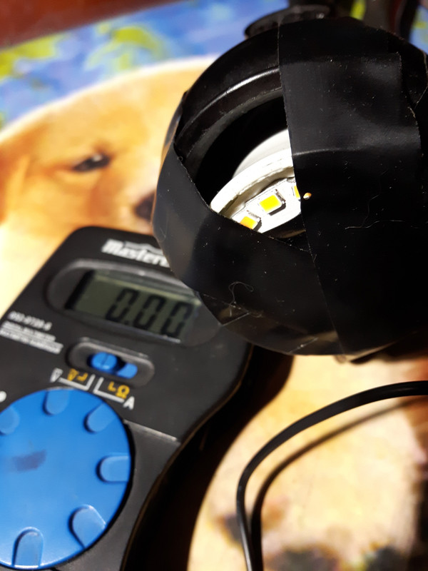
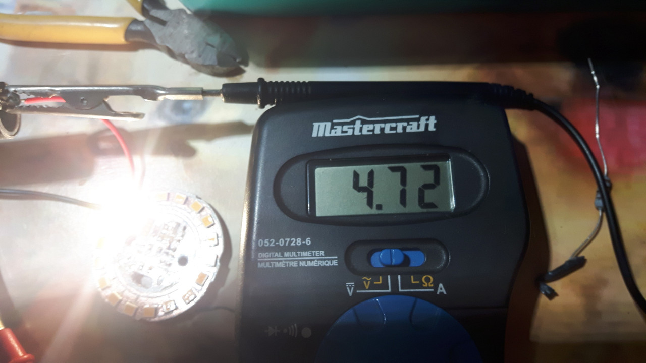
I removed all the circuits from the board and soldered wires to a single LED and powered it with a battery charger.
It lit with 3.98 V but I couldn't turn the voltage down any further.
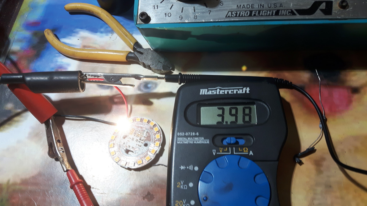
I turned up the voltage to 4.72 V and it got brighter but I couldn't turn it up any further.
(It's a current regulated supply not voltage)
It lit with 3.98 V but I couldn't turn the voltage down any further.
I turned up the voltage to 4.72 V and it got brighter but I couldn't turn it up any further.
(It's a current regulated supply not voltage)

