What's new

My home sounds like it's making pop corn...in the dark!

Hammerhead

Disabled Farmer
ICMag Donor
Veteran
You don't need to replace your cords just buy the male end and cut off the 120v male end. Thats what I did.. They where 4.80ea.. I painted the 240v red but still it only takes 1 mistake. why are you willing to risk that for 10$. Those universals are not UL approved. You can see in my pic that the ends in the 240v have been changed. I cant by accident plug in a 120v into a 240v or the other way 240v to 120v... Please make it safe for you


picture.php
 
Last edited:

Midnight

Member
Veteran
Using the C(R)AP receptacles is a huge mistake, in my opinion. There is not only the problem with the potential to plug in the wrong voltage equipment, but there is absolutely no way that those devices have passed any governing authority's testing (UL, CSA, etc) because they flagrantly disregard all existing standards. However, if you want to use cheap Chinese shit that has never been proven to handle the advertised load, good luck! Personally, I like my home in it's present configuration and fires scare the shit out of me, so I use nothing less than specification grade receptacles. Bear in mind that you are saving a grand total of about $10 by not replacing the cord caps on your two existing cords. *rant off*

If you are talking about 240v relays as being relays with double-pole contacts, fine, but that is the wrong terminology. However, if you are calling 240v relays (correctly) relays with a 240vac coil, you are going to have problems switching them with your timer.

*edit* If you insist on using the wrong receptacles, at least use a decent quality, UL approved receptacle and wire it with the wrong voltage. That way, if you burn some shit up it will be your own fault and not the fault of some poorly made off-shore crap made with inadequate materials and no performance testing. Hmmm....have I made my opinion of those receptacles clear enough?


I'm really glad you finally warned him about the fire hazard. I've been thinking the same thing through this whole thread...this dude is going to burn his house down. I sure hope not. I would highly recommend that the op look up "flame defender".
 

downtoearth

Member
Advice well taken. I have got a refund on those plugs. I hadn't realized they were this unsafe. I also like my home as is :) I'm just going to purchase the male ends and attach them to the existing 120v cords. I'm also looking up the flame defender Midnight. Thanks for that.

I have hired a licensed electrician to replace the old Federal Pacific breaker panel in my home. He's been in the field for over 30 years and still works as a full time electrician. He's replacing the 200 amp breaker panel for $200 even. Not too bad.

Thank you all again for keeping me on the straight and narrow. Really. :)
 

downtoearth

Member
Didn't get it.

Didn't get it.

If you are talking about 240v relays as being relays with double-pole contacts, fine, but that is the wrong terminology. However, if you are calling 240v relays (correctly) relays with a 240vac coil, you are going to have problems switching them with your timer.

I bought one of these for 120v and another identical in the 240v flavor.
http://www.pioneerbreaker.com/ProductDetails.asp?ProductCode=CN-PBC402-120V

I bought 2 of these for use with the above:
http://www.amazon.com/Aube-Honeywel...ZR8C/ref=sr_1_1?ie=UTF8&qid=1328849803&sr=8-1

Is the 240v relay going to pair up with one of the timers above? If not, is there a way to make it so? Thanks guys.:ying:
 

rives

Inveterate Tinkerer
Mentor
ICMag Donor
Veteran
That timer is not going to work with a 240v load - it has 3 connections, line, load and neutral. A 240v load requires a double-pole switch, meaning that both hot wires going to the load get switched. The only way to make it work would be to have the timer control a double-pole relay controlling the 240v relay - pretty messy and needlessly redundant.
 

downtoearth

Member
sheesh

sheesh

That timer is not going to work with a 240v load - it has 3 connections, line, load and neutral. A 240v load requires a double-pole switch, meaning that both hot wires going to the load get switched. The only way to make it work would be to have the timer control a double-pole relay controlling the 240v relay - pretty messy and needlessly redundant.

I canceled my Amazon order for ONE of these timers. I'll keep one for the other 120v service outlets that will be on this controller box. I'd be so fuckered without you guys helping me out with this. No doubt in my mind on this one. Do you have any suggestions as to what similar timer will work? I'm looking for 240v digital wall mounted timers now. I do realize that I could just get the plug in timers but I don't like them. And it's too easy lol. I want this controller box to be as seamless as I can get it.

*EDIT* I'm having a difficult time searching for a 240v digital in wall timers. Why can't things be simple lol. :)

*EDIT* Break time. Wondering how the guy from DX Hydro installs those timers for 240v service. :(

*EDIT* Back from break. I found this panel mount timer. What panel it mounts to I have no clue. I can't really pay too close attention to the one of two reviews because one guy didn't know how to install it properly and the other guy liked it just fine. Can one of you guys decipher the product description and let me know if this is an acceptable choice to wire onto this box for the 240v timed receptacles? http://www.amazon.com/gp/product/B0039Q7K1E/ref=ox_sc_act_title_1?ie=UTF8&m=ATVPDKIKX0DER

*UPDATE* As far as business goes, I have zero confidence in the dxhydro person. He can't be reached by phone, never returns phone calls, and when you email him, you get your email returned as undeliverable. I considered ordering one of his systems as this is getting to be a pain in my ass but now that isn't a possibility. I'll just chug along and get this done I suppose :(
 

MagicChef

Member
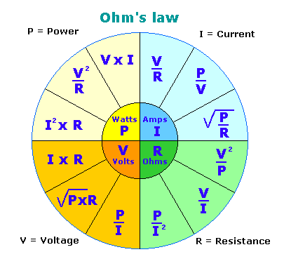
Your ballasts and lamps only pull about 8.3 amps each, not 9 for the ballast and 8 for the light. Also, you can get a device at lowes/home depot called a kill a watt. It's about $25.00, you plug it in the outlet and then plug whatever electrical devie you want to measure into it. It tells you exactly how much wattage that the device is pulling. From there just use ohms law to figure out your amperage, or you can just skip using the kill a watt and just use ohms law to begin with.

Image_C.jpg


ohms-law.gif


And for fire hazards i recommend one of these. Please excuse the cheesy porn music.
[youtubeif]STjMZz8gxbA[/youtubeif]

This isnt entirely true. You do have copper losses on your ballast. You would be lying if you said the lamp draws EXACTLy the same as the ballsat. There are operational losses with the ballast as well.
 

rives

Inveterate Tinkerer
Mentor
ICMag Donor
Veteran
I canceled my Amazon order for ONE of these timers. I'll keep one for the other 120v service outlets that will be on this controller box. I'd be so fuckered without you guys helping me out with this.

*EDIT* Break time. Wondering how the guy from DX Hydro installs those timers for 240v service. :(

*EDIT* Back from break. I found this panel mount timer. What panel it mounts to I have no clue.


You are making this way too difficult. If you simply use the timers that you had picked out, and use them to drive DPDT power relays with 120vac coils (link below, same as earlier post), then you can switch any load or voltage that you will have in your grow. This way you will have standardization of components, and can have minimal spare parts around in case something dies.

To clarify this a little bit, if you have a DPDT relay (DPDT means Double Pole, Double Throw), you can use it to drive (2) 120 loads at the same time - there are two sets of contacts, and you can set it up so that each set of contacts can power (2) separate 120v devices when the timer output is turned on and another (2) separate 120v devices when the timer is turned off. For instance, if you wanted to turn on a particular fan at lights off, you could drive easily turn on (2) different ballasts during lights on and the above fan when the lights go off, all with one timer and one relay.

This same arrangement could be used to drive a 240v load. Both hot wires on a 240v load are required to be opened and closed simultaneously when turning it on and off, so the DPDT relay could turn on (1) 240v load when the timer is output is turned on and a different 240v load when the timer output is off.

This type of relay uses what is called a c-form contact. Envision a contact point at each open end of a "C", with a moving contact placed between them. Spring tension holds the moving contact (common) and one stationary contact together when the relay is not energized, giving you a normally closed (N.C.) contact. The N.C. contact allows you to apply power to something when the relay is off.

When the relay is energized, the relay coil becomes an electromagnet that overcomes the spring tension holding "C" and "N.C." closed, and moves "C" over to the "N.O." contact, turning on whatever you want when the timer has turned it's output on.

Your hot wire(s) will attach to the "C" terminal, and the loads will attach to the "N.O." and/or "N.C." terminals depending on what you want to happen.
This may sound confusing, but it will become very obvious when you get the parts in your hand. Hope this helps!

The 240v timer that you found apparently has to be mounted on a special backplane to function. A search of the Intermatic site didn't result in any functional links, but it has pretty low reviews from people that have tried to use it. Do the above!

http://www.automationdirect.com/adc...n-Style,_40A_(AD-PR40_Series)/AD-PR40-2C-120A
 
Last edited:

downtoearth

Member
I do have a tendency of making things harder for myself by thinking way to hard about it. I couldn't stop the two timers from shipping out anyhow. I'll just accept them and use them. Can't thank you enough. :)

I ordered the two that you listed for simplicity sake. cheers!
 

Hammerhead

Disabled Farmer
ICMag Donor
Veteran
you dont need a seperate timer for your 240v.. when you hook up the control box it will be wired for 240 and 120...these get hooked up to the relay. the trigger goes to the single cheap timer on 120v. This will switch on the relay and pass the juice to 240v and 120v outlets. This schematic shows everything except where the trigger wire get connected to the relay. Line side of the relay is hot the load side is not energized until the trigger from the timer goes off. If you want something to turn on at a different time then the first relay you will need a 2ND relay... When you get all the parts its very easy to assemble


picture.php
 
Last edited:

downtoearth

Member
Just an update. Just making sure with you guys but 12 gauge wire for 20 amp service and 14 gauge wire for 15 amp service. Not sure of the gauge used for the 100 amp run into the sub panel just yet.
 

Hammerhead

Disabled Farmer
ICMag Donor
Veteran
To make it simple I used all the same size wire for all of the breakers. 12g is fine for 20a.. If you use all 12g if you needed to upgrade that 15a to a 20a the wire wont need to be changed..I used 10g I know its over kill thats fine. I like it to be better then what is should be.

Im pretty sure 100a service is #2 wire.. rives can verify that...
 

downtoearth

Member
I will use all 20 amp breakers and 12g wire. How many 20 amp breakers should I get for my sub panel? It's a 100amp, 10 spaces, & 20 circuits. Here is the setup.

Two 120v in-wall timers
Two Duplex 240v timed receptacles
Two Duplex 120v timed receptacles
Ten Duplex 120v constant power receptacles
 

downtoearth

Member
I'm going to be running 3 ballasts switched to 240v. What in your opinion would be best? Hooking two of these ballasts into one double pole 20a breaker and then hooking the third into one more double pole 20a breaker by itself? Or just get three double poles and hook one ballast into each breaker?
 

Hammerhead

Disabled Farmer
ICMag Donor
Veteran
I think you need to have ea ballest on there own breaker. 2 on a 20 is over the 80% rule... Im not 100% sure on that so rives will need to answer that one

8.42a x 2 =16.84a 20a-80%=16a
 
Top