I'm working on it.....A few pics in the mean time.
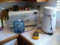
There are three power cutoffs with this model, the Megahome distiller has just the reset and a fuse.
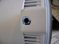
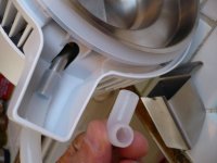
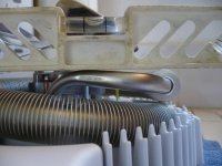
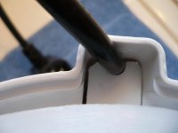
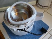
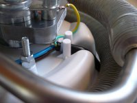
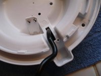
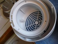
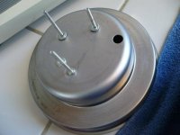
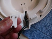
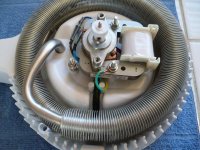
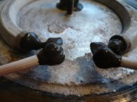
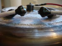
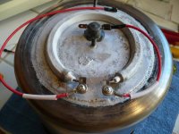
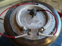
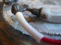
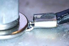
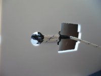
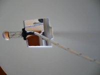
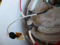
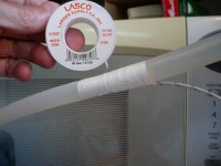
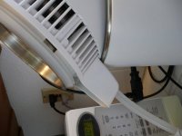
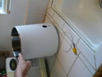
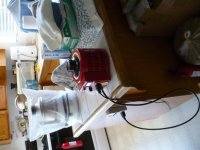
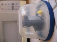
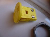
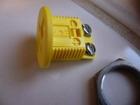
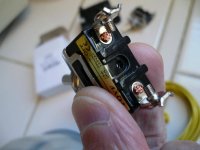
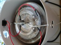
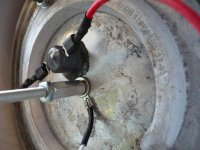
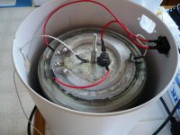
In the overview pic you can see on the side of the can the 115C/239F Power reset temp cutout, in the middle is the 150C/302F over temp cutout, and the pic showing me holding a wire soldered to a ring terminal is the fail safe cutout (the solder melts letting the wire go free - it's not crimped.)
I'm eliminating much of it and adding a thermocouple, full details in a few days.
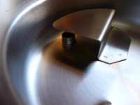
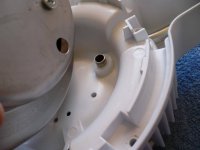
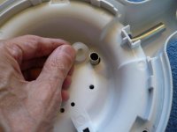
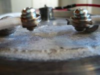
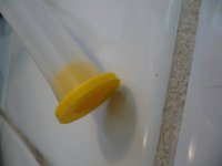
What I want everyone to see is the inside of the Power reset temp cutout. The fit of the reset shaft is sloppy, worse than I imagined, and the back side isn't a perfect seal either. It's being eliminated, I don't need it for my purposes, and it's a potential ignition source. Why I suggest examining any electrical device before repurposing it.
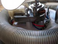
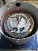
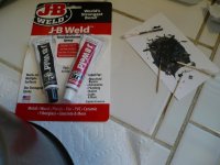
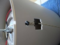
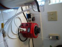
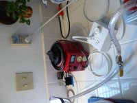
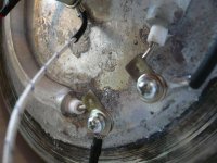
I doubt anyone has had a fire from recycling ethanol in these off the shelf, but if you have the know how, you can do better. I'm J-B Welding the over heat cutout directly to the middle of the can right now, hot rodding it so to speak.
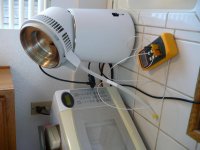
The condenser is also getting a thermocouple temp sensor.
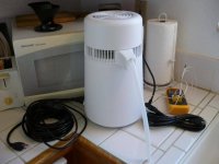
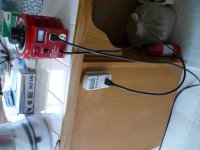
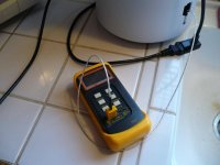
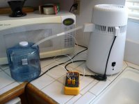
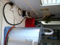
Same plan, power meter > Variac > distiller with temp readings.
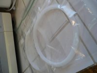
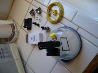
Btw, I received some exact replacement seal/gaskets, two for ten bucks direct from China,
https://www.ebay.com/itm/2PCS-Seal-...e=STRK:MEBIDX:IT&_trksid=p2060353.m2749.l2649

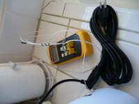
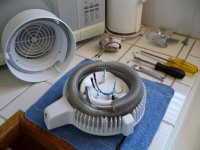
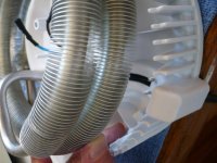
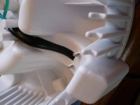
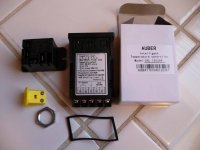
Here's some pictures of the wiring minus the low cutout, and the other extraneous pieces. As mentioned in the quote, you could leave it unmodified, or just bypass the low cutoff by connecting it's leads together.
The ring lug K thermocouple is just an ordinary thermocouple crimped at the insulation to a cheap terminal, I'm making a simpler, faster reading, and more robust replacement by potting a K thermocouple to a high quality ring lug using J-B Weld, pictures later.
I did a dry test, the cutoff and sensor both seem to be well placed based on my my IR gun readings.
The Variac control is smooth, and the power meter slick, 60 watts provides a steady 250F for decarbing, and only 100 watts quickly triggers the 300F cutout.
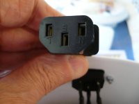
In the pictures you can see the appliance cord plug is labeled Neutral, Line, and Earth. They chose to put these two over-temperature disconnects in the Neutral line, I'm assuming the logic is if the solder gets hot enough to flow, and the 'fail safe' wire comes free, you want it to be the Neutral. I figure if it ever gets that hot the solvent should be gone, and there is something wrong, you need it to shut down.
Attachments
Last edited: