What's new

Growroom Electricity and Wiring

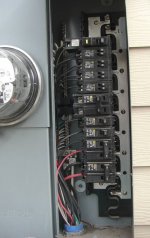
When feeding sub-panels, you need to use SER cable. All grounded (neutrals) and grounding (grounds) conductors need to be isolated in a sub-panel. If you guys look at your main panel, you'll probably see both grounds and neutrals terminated to the same buss bar. Don't do this in a sub-panel.

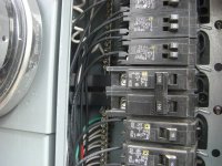
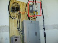
Here is a MLO panelboard (Main Lug Only sub-panel) fed with, what looks to be 6 or 8 gauge romex. If it's #6 CU romex, then you have to use no larger than a 60A double pole breaker in your main panel. If it's #8 CU romex, then no larger than a 40A double pole breaker in your main panel.
picture.php


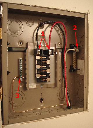
1. The ungrounded conductors (red and black) are connected to the top 2 main lugs which in turn feed the hot buss bars.
2. The grounded conductor (white) is connected to the large lug on the neutral buss bar. The neutral buss will be isolated from the frame of the panel. Notice this panelboard has 2 neutral buss, the other one is hiding to the left.
3. The grounding conductor (no sheathing) is connected to the ground buss. This will be directly fastened to the panel frame. Some panelboards don't come with a dedicated ground buss. You must purchase and install it separately if not. I also don't like the location of that ground buss. Too close to the hot and neutral buss. I would have put it down below.

Here's a close up of the isolated neutral buss:
picture.php

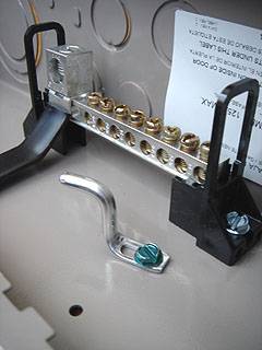
Notice the bonding bar with the green screw. Remove this entirely. Some panelboards will come with a thin bonding strap, others will come with a long green grounding screw. It's to bond the neutral bus to the frame of the panel if you are using the panelboard as a main panel. In that case, you would loosen the screw, rotate the bar to the right and put it under one of the terminals on the neutral buss, then tighten down both screws. Don't do this on a sub-panel.

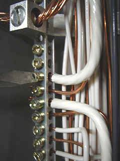
So, to connect the feeder cable in your main panel, attach your grounding wire first. This will more than likely get terminated to your neutral buss in the main panel as will the neutral wire of our feeder like so:
picture.php


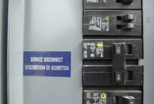
If your neutrals and grounds are separated in your main panel, this likely means you have an outside disconnect right below the meter. That means your main panel is actually a sub-panel!!! If that's the case, then you would tie the ground wire for your new sub-panel feed onto the isolated ground buss in your main panel.

Hope I didn't loose anyone there.But... If all your neutrals and grounds are terminated to the same buss bar in your main panel, both the neutral and ground of your sub-panel feed get terminated to your main panels neutral buss bar as the pic above shows.


so When i wired up my sub panel as described above, it throws the breaker on the main panel as soon as i try to turn it on. If i attach the included screw that grounds the neutral bus bar, then the sub panel and the circuits ran from it work. (I only tested the 120 outlets, not the 240) What does this mean? I have the breaker off at the main panel for now, till i get a definitive answer. I also have a friendly electrician coming over in the next 1 or 2 days for a different reason, but i'll have him take a gander at this as well.
 

madpenguin

Member
IF my house's main service is a "subpanel", and it has the ground and neutral bus's connected, what should i do?

Who ever wired your "Main Panel" fucked up then. That or your using the term "subpanel" incorrectly. If your "main panel" is the first means of disconnect and there is no other main breaker upstream like outside by your meter, then your main panel IS NOT a subpanel, it's actually your main panel and your grounds and neutrals SHOULD be connected. If you have an outside disconnect and then cable comes from that into your "main panel" inside, then yes.... Someone fucked up and your grounds and neutrals should be separated in the "main" panel.

i wired up junction box before the dryer outlet, and then tested it, and the dryer still works so i know that junction box is legit. then i wired my light timer and outlets to the sub panel,
Is this a new subpanel you just installed or actually your "main panel"? You keep using the term "subpanel" so I don't know how many you actually have.

and finally attached the leads to the sub panel. when i try to turn the breaker on in the main panel, it trips immediately. This happens when all of the breakers in the sub panel are off. After being stumped last night and stopping on it for the day, i decided to day to look in the main panel and my suspicions were correct. Could this ground/neutral shared bus in the main panel be causing my sub panel to not work?
You have a fault occurring plain and simple your main breaker is doing it's job. This is something I really can't say "Aha! there's your problem" with out looking at it.

The only thing sharing grounds and neutrals will do when your not supposed to is give an alternate path for return current to travel on (the ground wire).

I'm a little more than confused because basically your saying everything in your house is a "subpanel", even your main panel. If your grounds and neutrals are all attached at the same point in your main panel then it's NOT a subpanel.

This is the very first thing I would do in your case. Remove that bonding bar in the new subpanel you just installed so your neutral bus is isolated from the frame of the panel like it should be. Get a multimeter and put it on the 300V setting. Measure between the incoming neural in your subpanel and one of the incoming hots. Then do the same thing with the neutral and the other hot. Then measure between the ground and the neutral, measure between the ground and one of the hots and measure between the ground and the other hot.

Measure ALL possible combinations and tell me what you get.

I really could use some pictures as well. Trouble shooting something like requires hands on. I just can't do that. But the volt meter test should be done between all points like I described. That will more than likely reveal your problem.

Also your junction box at the dryer receptacle works but you have problems after that. That's a point where I would also take multimeter readings between all points.
 
Who ever wired your "Main Panel" fucked up then. That or your using the term "subpanel" incorrectly. If your "main panel" is the first means of disconnect and there is no other main breaker upstream like outside by your meter, then your main panel IS NOT a subpanel, it's actually your main panel and your grounds and neutrals SHOULD be connected. If you have an outside disconnect and then cable comes from that into your "main panel" inside, then yes.... Someone fucked up and your grounds and neutrals should be separated in the "main" panel.

Is this a new subpanel you just installed or actually your "main panel"? You keep using the term "subpanel" so I don't know how many you actually have.

You have a fault occurring plain and simple your main breaker is doing it's job. This is something I really can't say "Aha! there's your problem" with out looking at it.

The only thing sharing grounds and neutrals will do when your not supposed to is give an alternate path for return current to travel on (the ground wire).

I'm a little more than confused because basically your saying everything in your house is a "subpanel", even your main panel. If your grounds and neutrals are all attached at the same point in your main panel then it's NOT a subpanel.

This is the very first thing I would do in your case. Remove that bonding bar in the new subpanel you just installed so your neutral bus is isolated from the frame of the panel like it should be. Get a multimeter and put it on the 300V setting. Measure between the incoming neural in your subpanel and one of the incoming hots. Then do the same thing with the neutral and the other hot. Then measure between the ground and the neutral, measure between the ground and one of the hots and measure between the ground and the other hot.

Measure ALL possible combinations and tell me what you get.

I really could use some pictures as well. Trouble shooting something like requires hands on. I just can't do that. But the volt meter test should be done between all points like I described. That will more than likely reveal your problem.

Also your junction box at the dryer receptacle works but you have problems after that. That's a point where I would also take multimeter readings between all points.

First, I have pics of the main panel. regardless if this is actually a sub, it will now be referred to as the main panel. "sub panel" will only be used to discuss the small one i am installing for the grow.

Okay, i have a multimeter but if i isolate the neutral bus in the sub, it throws the breaker on the main, so i had to do the first round of tests with the neutral bus of the sub grounded. I had assumed that since power was coming through outlets after the sub panel that power was getting to it fine, and that since the dryer was running then everything on that side of the junction was peachy. After testing with my meter, the black to ground or white =118v, and the red was nothing! i didnt realize the dryer would run without half of its 240 power. I went back to the junction box, checked all connections, and yes there was a red wire that got twisted out when shoving the wires into the junction box, so i redid and tested all those connections, isolated my neutral bus on my sub, and tried to turn on the breaker on the main. it threw.

So i disconnected all leads from my sub panel and then tried to turn the breaker on the main panel on, it worked. i tested all things i could, In the dryer receptacle- red-white=120,red-green=120, black-white=118, black-greeen=118. These are the same readings i got from all the connections in the junction box, as well as the readings from the open leads coming to the sub. white-green readings were always 0.

anyways, heres the pics of the main. There is the SERVICE DISCONNECT sticker and that 100A breaker controls the whole house.
 

Attachments

  • main1.jpg
    main1.jpg
    45.8 KB · Views: 14
  • main2.jpg
    main2.jpg
    50.5 KB · Views: 12
  • main3.jpg
    main3.jpg
    71.6 KB · Views: 16

madpenguin

Member
First, I have pics of the main panel. regardless if this is actually a sub, it will now be referred to as the main panel. "sub panel" will only be used to discuss the small one i am installing for the grow.

As it should. Your main panel right next to the meter has your main disconnect (the 100A breaker). That looks to feed the entire bus bar in that panel. Throw that 100A and all those other breakers should go dead. Neutrals and grounds should be on the same bus bar in that panel, just like they already are.

Okay, i have a multimeter but if i isolate the neutral bus in the sub, it throws the breaker on the main,

Turn ALL the breakers off in your new subpanel for the grow room. Then turn the 30A main for the sub back on. Let me ask you this... Are you running any 240v loads or are they all 120v on your new subpanel?

so i had to do the first round of tests with the neutral bus of the sub grounded. I had assumed that since power was coming through outlets after the sub panel that power was getting to it fine, and that since the dryer was running then everything on that side of the junction was peachy. After testing with my meter, the black to ground or white =118v, and the red was nothing! i didnt realize the dryer would run without half of its 240 power. I went back to the junction box, checked all connections, and yes there was a red wire that got twisted out when shoving the wires into the junction box, so i redid and tested all those connections, isolated my neutral bus on my sub, and tried to turn on the breaker on the main. it threw.

So i disconnected all leads from my sub panel and then tried to turn the breaker on the main panel on, it worked. i tested all things i could, In the dryer receptacle- red-white=120,red-green=120, black-white=118, black-greeen=118. These are the same readings i got from all the connections in the junction box, as well as the readings from the open leads coming to the sub. white-green readings were always 0.[/quote]

Dude... Those are all correct readings and are exactally what they should be.

Give me the low down on any 240v shit your running off the sub. Fuck this pisses me off. You have to bond the neutral to the frame of the panel (which is grounded) in order for it to work. That makes no fucking sense. Your neutral is "grounded" and that's why you get 118v from black to white and 118v from black to ground. Because your bare ground and the white neutral are at the same voltage potential, which is zero.

I'm going to pull my hair out on this one. Wish I could be there. Could probably find out what's going on in 20-30 minutes but right now it's just not logical.

Give me the low down on the 240 loads that your new subpanel supplies and how they are hooked up and I'll think about it some more.
 

madpenguin

Member
if i isolate the neutral bus in the sub, it throws the breaker on the main

This is making a little more sense. My guess is you have a ground fault downstream from your subpanel in the grow room. I know it sucks but your culprit likely lies with a receptacle in your grow room. You didn't shove one of the grounds all the way back into the gang box before pushing the neutral and hot in. So a bare ground touching a receptacle screw might be tripping not only the breaker that controls it in your subpanel (check for this!!!) but often times the fault current is so high, it will also trip the main breaker for the sub upstream.

Inspect all your junction boxes and receptacles in the grow room. I might be willing to bet you'll find an issue there because all your multimeter readings were freaking spot on. That can really only mean that it's downstream of your subpanel if your receiving all the correct voltages at the sub with all the wires just hanging loose.
 
so, after finding and correcting the loose red like i did before, i cannot maintain power to the sub at all. I've tried grounding, isolating the neutral bus, checked connections and junctions and receptacles, right now i have no breakers and no wires in my sub except the leads, and it still wont stay on, neutral isolated or not. I have to completely disconnect my sub to have the circuit even on to be able to use the dryer.

i havent tried to use any 240 from the sub yet, i only have the digi ballasts and they're sensitive, so i'm waiting till this is all stable to plug them in. There is a mech timer inline before them(grounded case) and the receptacles are in metal boxes w/ lids (grounded). after thinking about what you said, i went and disconnected all the grounds from the sub too. i had been testing it with the breakers pulled out, but the grounds still attached, i thought that might have been it but i took them off too and it still wont maintain.
 

Tilt

Member
a quote i did on another thread.

did a sub panel today. I have a few suggestions
1. do not bond the nuetral bus bar to the panel(nuetrals must be isolated in sub panels)
2. buy a ground bar to land your grounds to 10/32 machine screws to metal of can (tapping set at harbor freight $10.00)
3. Make your final connections at your main panel the last thing you do before energizing your new panel
3. Use a multimeter before turning on the sub panel set to ohms
a. should have continuity nuetral to ground
b. should have no continuity between hot wire #1 to hot wire #2 or between any hot wires and nuetral or between hot wires and ground
4. use multimeter after panel is on set to ac voltage
a. hot wire #1 to hot wire #2 should be 240 volts nominal
b. either hot wire to nuetral 120 volts nominal
c. either hot wire to ground 120 volts nominal

I suggest turning off your main power when working in your main panel.When you turn on power to a breaker use 1 hand stand to 1 side of the panel and look away. This is to protect you from arc flash.

If I was doing a service call after what you described.
1. I would isolate the wiring to the sub panel turn off all breakers in sub panel
2. use my multi meter set to ohms check hot #1 to hot #3 (if there is continuity you have a phase to phase short)
3. check hot #1 to nuetral (if there is continuity you have phase to nuetral short)
4. repeat for hot #2
5. repeat check hots to the ground (if there is continuity you have a phase to ground short)
6. check for continuity nuetral to ground you should have continuity if it is bonded correctly at the main panel
start with this and we will see where we are at
 

Tilt

Member
I don't want to step on penguins toes. I'm just trying to help out. I do a lot of trouble shooting. please be safe.
 
a quote i did on another thread.

did a sub panel today. I have a few suggestions
1. do not bond the nuetral bus bar to the panel(nuetrals must be isolated in sub panels)
2. buy a ground bar to land your grounds to 10/32 machine screws to metal of can (tapping set at harbor freight $10.00)
3. Make your final connections at your main panel the last thing you do before energizing your new panel
3. Use a multimeter before turning on the sub panel set to ohms
a. should have continuity nuetral to ground
b. should have no continuity between hot wire #1 to hot wire #2 or between any hot wires and nuetral or between hot wires and ground
4. use multimeter after panel is on set to ac voltage
a. hot wire #1 to hot wire #2 should be 240 volts nominal
b. either hot wire to nuetral 120 volts nominal
c. either hot wire to ground 120 volts nominal

I suggest turning off your main power when working in your main panel.When you turn on power to a breaker use 1 hand stand to 1 side of the panel and look away. This is to protect you from arc flash.

If I was doing a service call after what you described.
1. I would isolate the wiring to the sub panel turn off all breakers in sub panel
2. use my multi meter set to ohms check hot #1 to hot #3 (if there is continuity you have a phase to phase short)
3. check hot #1 to nuetral (if there is continuity you have phase to nuetral short)
4. repeat for hot #2
5. repeat check hots to the ground (if there is continuity you have a phase to ground short)
6. check for continuity nuetral to ground you should have continuity if it is bonded correctly at the main panel
start with this and we will see where we are at


thanks so much for taking the time to post these troubleshooting tips, i'll try these soon and report my findings. I'm sure MP wont mind you chiming in, your advice is sound and safe and he likes others to help out a bit.
 

micro420guy

Member
I have an electrical question. I bought some digital ballasts online that state to only us 18aw solid wire. I went to the crappy tire and bout some 18aw thermostat wire because thats all they have in that gauge and solid strand.

My question is will this work for T5 2g11 ballast and socket set up? The wire I bought stays 150volts max on the box and the short pieces that came with the ballast say 600v on the wire casing. I don't understand why the wire would be rated for 150v??? isn't wire rated in amps not volts????

Thanks in advance.... micro.
 

Tilt

Member
wire can be rated for alot more than just amps voltage wetness uv resistance etc. The voltage rating I believe is based upon the type and thickness of insulated jacketing. T stat wire like 18/8 has a very thin insulation. Tstat ussually dont go much higher than 24 volts ac. 18 awg is large enough to carry the current with out melting the copper but the insulation is so thin that the voltage can overcome the jacket and short out. Get some 18 awg thhn or thwn and you will be fine.
 
okay, i got the whole sub panel figured out, it was basicly just me being an idiot. I had the red lead connected to the neutral bus bar, because the reds screw was hidden behind some plastic. I had been testing everything over and over again, and then when tilt mentioned the ohm test, i figured it out as i was looking at different things to test and connect. Now it is running swimmingly, 120 and 240 outlets checked, 240 timer and outlets going great. as a side bonus of this stupid mistake, i have checked all my connections multiple times and they are all SECURE and i have also learned the full functions and applications of my multimeter.
 
next project, exhaust fan for my work shop. As you can see from the first photos, this fan has some wiring and the switch with plastic switchplate very exposed. i will be ventiliating hot stuff (torch and kiln exhaust) so would like to protect it. My plan is to remove this switch thats on there, and move the junction box closer to the motor. I'll put those wires directly into the side of hte junction box, as well as that black box. Then i'll attach some flexible metal clad cable to the junction box. from there, ill either run this metal clad cable into a junction box w/ a dimmer switch, and a flexible extensino cord coming out to plug in; or ill run the conduit to a junction box and hardline it into the circuit, and run a line w/ just the dimmer switch to the front of the bench (either the flex extension cord, or more flex metal clad.

The first photo shows the fan as it arrived.

The second photo shows the exposed wires.

the third photo shows inside the junction box as it came.

the fourth photo shows one side of the 3 speed switch, with 2 wires going in, and 2 wires going out to be connected to power.

The fifth photo shows the other side of the switch, where the other 2 wires go into the switch.

My questions are:

1. can i assume that the blue wire in the group of 4 coming from the motor is ground(green)?

2. If i remove this 3 way switch, do i need to run 4 wires through the metal clad to connect to each? if i do, what do i connect the 4 wires to, when theres only 3 in the extension plug or a normal circuit?

If its going to be a hassle to convert from the 4 wires to 3, i can just run an extra wire through the metal clad, and run all 4 lines through it, then have the included pull chain switch at a remote junction box (front of the bench).
 

Attachments

  • fan1.jpg
    fan1.jpg
    64.9 KB · Views: 12
  • fan2.jpg
    fan2.jpg
    62 KB · Views: 17
  • fan3.jpg
    fan3.jpg
    76.8 KB · Views: 12
  • fan4.jpg
    fan4.jpg
    52.1 KB · Views: 12

Avenger

Well-known member
Veteran
1. can i assume that the blue wire in the group of 4 coming from the motor is ground(green)?

No. Your motor is a three speed motor. black is probably high speed, blue is prob medium, red is prob low speed. White is the common or neutral.

the switch is for changing the fan speed.
 
cool thanks for the prompt response, that make sense.

so if i dont care about adjusting the speed, and find 1 of the three that is a good constant speed, i could direct wire just 1 of the leads, or run an extra line through the MC and run all of the wires down to the junction box, and have the included switch there.
 

Avenger

Well-known member
Veteran
Yes, just make sure to cap off the unused speed leads if you go that route, as there will be voltage on them.
 
any electrician no what this huge relay is called? Shuts the whole panel down if there's a problem. or a website where i can order it?
thanks
:dance013:
 

Attachments

  • PG081508hf.jpg
    PG081508hf.jpg
    25.5 KB · Views: 16

Latest posts

Latest posts

Top