madpenguin
Member
Cool. Always been intrigued by vertical setups. Looks good.

Not sure if anyone has covered this yet, but I will ask anyway.
I saw a tutorial about them in here but it didn't cover solid state relays.
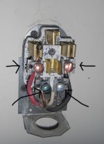
Sure. This is a 40A Intermatic HD timer your talking about? If your just using the #8 copper romex coming from the timer to the relay (yes, use #8), then you'll not only need to terminate the incoming wires to the "line in" contacts of the relay, but you'll need to pigtail or jumper from the same "line in" wires over to the "center contacts" in order to operate the relay and send power to the "load out" contacts once the 40A timer turns on and sends power out towards the 60A SSR.My question is; can a 60amp solid state relay be used after a timer?
Question, Are you using 40A single pole breakers or 40A double pole breakers. By the amperage you are giving it has to be 120v lighting but you would probably be better off using a DP 40A breaker with 8/3 as the feed.my basic design is a GE 120v, 200amp panel from the meter with 3/0 awg. There will be nothing except for the room wired to this panel. I have 1x 40amp circuit wired to a 40amp timer that is wired to 3 receptacles. 3x 40amp circuits are wired to 5x receptacles, 2x 20amp circuits are wired to 2x receptacles.
So from the 40amp circuit i am wiring to a 40amp timer and inside the (timer)box i wish to wire a 60amp (only one i could find at the time) relay after the timer then on to the receptacles. I am gonna be running 4x 1000w ballasts and a 200w exhaust fan on this circuit. it will run about 35amps on a continues load (12hrs).
hhmm, should I split the load on to 2x 40amp circuits?
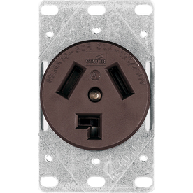
the plugs on my lamps are the 6-15r shape. i have found recepticles in this shape that are 15A, and 20A. i saw earlier in this thread you mention a 6-30r outlet, is this large like for dryers? its the same config as my plugs, but looks much bigger. IF my lamp plugs are 6-15r, does this mean i can only use a 15A outlet and thusly a 15A breaker? that makes 4 6ers or 2 1k's on one circuit or mech timer. now i see why people are using relays and 120v timers. if you cut the plugs off your lamps, and hardwire them directly to the timer or circuit, does this eliminate the recepticle roadblock and allow you to use straigh 30A from the timer? (or 40A if you were doing say 6k)

")
Yes, your right. A 30A receptacle is as big as a dryer receptacle you'd have to be damaged in the brain to snip all your ballast plugs and rewire them with a 30A plug.... I stated in the beginning of this thread I make mistakes on occasion and that was one of them...
When talking with Avenger on another thread he inadvertently led me to an article in the NEC that states you can hook 20A receptacles up to a 30A run. I really wish I would have bookmarked that f'er. I think it was in 400 somewhere.
The choice is yours. Just know that when dealing with electricity, there really is no such thing as "overkill". It's actually called "being safer".
Hold on for the Article number. I'll post it so we can all see what the NEC has to say about it.
One question, when running the 20A receptacles on 30A, using 12 wire, can i wire them in a series from one to the next, or should i make a pigtail split into 4 lines from the timer and feed each outlet separately?
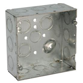
I have another question about grounding. it seems fairly straightforward, always connect your grounds to the other ground wires, and to ground screws in your junction boxes if using metal. I am using metal, and i'm wondering if you have to connect anything more than that? if the wire's attached to the junction box, do the junctin boxes need to be connected to each other, and/or have a physical wire that goes to the ground or cold water pipe? one ground wire for the whole panel? or does it go back through the panel and get its ground from the main panel? I just dont want to get this whole thing assembled and then have to go back.
Yea... Ballasts in general should be grounded else you'll start getting some screwy shit happening, such as they wont fire properly. This really is noticeable with florescent ballasts in particular.I dont want to sound totally retarded, cause i've wired a few circuits before, but its been a while. everything has always worked on them, except my digi ballasts. I know theres a chance that it was just ghetto ballasts, theres also a major chance it was just bulb compatibility issues. Still, i have heard of improperly grounded circuits getting the digi ballasts in a way that doesnt affect other appliances.
Not sure if anyone has covered this yet, but I will ask anyway.
I saw a tutorial about them in here but it didn't cover solid state relays.
My question is; can a 60amp solid state relay be used after a timer?
my basic design is a GE 120v, 200amp panel from the meter with 3/0 awg. There will be nothing except for the room wired to this panel. I have 1x 40amp circuit wired to a 40amp timer that is wired to 3 receptacles. 3x 40amp circuits are wired to 5x receptacles, 2x 20amp circuits are wired to 2x receptacles.
So from the 40amp circuit i am wiring to a 40amp timer and inside the (timer)box i wish to wire a 60amp (only one i could find at the time) relay after the timer then on to the receptacles. I am gonna be running 4x 1000w ballasts and a 200w exhaust fan on this circuit. it will run about 35amps on a continues load (12hrs).
hhmm, should I split the load on to 2x 40amp circuits?