What's new

Off the shelf retail store screw-in LED and CFL bulb comparisons

Hookahhead

Active member
I caught an error after looking at the pictures. I was measuring DC, but had the probes hooked up to the AC side. So I switched the probe around and tested it again. 0.00 and the lights didn’t light up. Remove the probe and the lights turn on.

I’m a little confused by this, the PCB should be an AC to DC converter to drive the LEDs right?

I switched the probe and the dial back to AC.
It reads 227w AC with two boards joined together.

picture.php


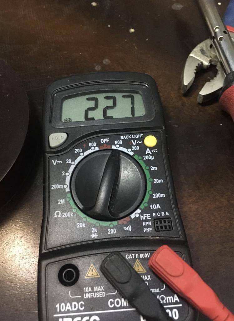
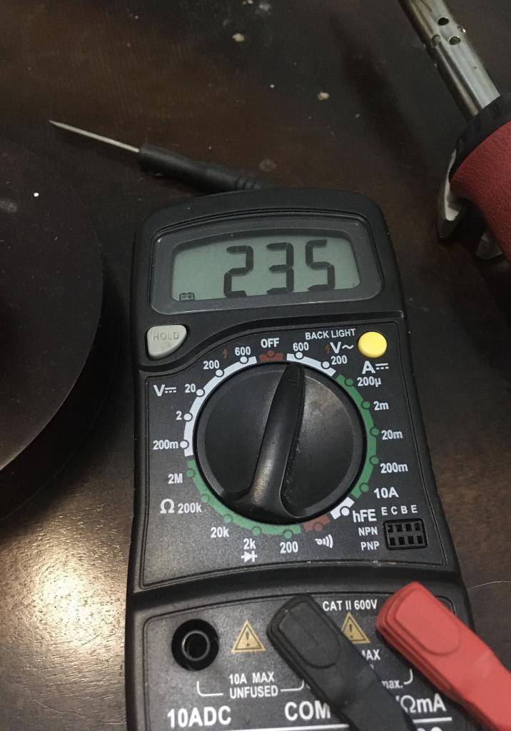
I desoldered the second board and tested only a single board. 235w AC?

picture.php


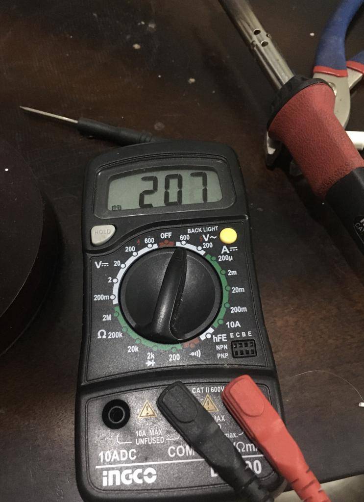
I switched the probe and the dial back to DC and tested only 1 board. Again it read 0 and didn’t light up, the board would light up when the probe was removed. At one point I slipped and I think I shorted the positive and negative. After this the LEDs started noticeably flickering and looked less bright. Switching back to AC again to take another reading shows 207w AC.

picture.php


Obviously this driver is bad and I don’t feel safe running it anymore. It was the clean board too. Looks like I’ll get some numbers from the other driver soon.

I hadn’t really planned to do all this testing, but when I opened the bulb and the board fell out it made me want to investigate more. I had hoped to mount these 4 boards to a small piece of aluminum and use them over some clones. This will be on a shelf, so the extra head room by eliminating the bulb and socket is kind of necessary. I’m not really concerned about running the boards remotely or the heat they generate. Where this would actually be practical is if you had a meanwell or similar driver pushing multiple of these boards.

Edit: I just realized I keep writing watt in these posts when I actually mean volt... smh
 

indagroove

Active member
Veteran
I caught an error after looking at the pictures. I was measuring DC, but had the probes hooked up to the AC side. So I switched the probe around and tested it again. 0.00 and the lights didn’t light up. Remove the probe and the lights turn on.

I'm not familiar with your specific tester, but generally you do not need to change the probes to test AC vs DC voltage, you only need to change the switch. You need to change the probes to measure DC current (not voltage). It does look to me that the left side plug in for your tester is to measure DC Amperage (above 200mA?), not to exceed 10 amps, hence the 10ADC denotation. Might check the manual to be sure.
 

PCBuds

Well-known member
I guess you're 240 V where you are.

The power comes in one side of the PCB as AC ~207 V then gets converted into ~105 V DC.

You measured correctly the first time @ 102&107 V DC, but when you had your multimeter turned to AC and tried to measure DC the meter probably kinda "shorted" out the circuit.

You can't really join two drivers together, except at the AC input.
The outputs need to be separately connected to a separate LED board.

If the outputs are connected together, they interfere with each other and you don't double the drivers' power.

One driver can drive two LED boards but two drivers can't power one or more LED boards.
Especially if they aren't identical circuit boards/drivers.

I don't know if Meanwell makes a driver that puts out ~100 V?

My driver is 24V because my 2' LED strips are 19.5V.
There is a 48V driver that would be needed for the 4' strips.


EDIT: Yeah, they make one.

$90 CAD plus shipping taxes and duty.


PCBuds

Well-known member
I'm not familiar with your specific tester, but generally you do not need to change the probes to test AC vs DC voltage, you only need to change the switch. You need to change the probes to measure DC current (not voltage). It does look to me that the left side plug in for your tester is to measure DC Amperage (above 200mA?), not to exceed 10 amps, hence the 10ADC denotation. Might check the manual to be sure.

Yeah, that's how mine works.

The probes plug into the same spot except for 10 A max. (mine has a second input for 0.4 A max.)

If you had your probe plugged into the 10 A input you would short circuit the circuit board.
 

PCBuds

Well-known member
... I was measuring DC, but had the probes hooked up to the AC side....

It doesn't matter if you try to measure AC with the meter set to DC or vice versa.

You'll just get a reading of 0.

In electricity class (house wiring), we were told to always measure amps across a switch to prevent us from short-circuiting the power source.
 

indagroove

Active member
Veteran
It doesn't matter if you try to measure AC with the meter set to DC or vice versa.

You'll just get a reading of 0.

In electricity class (house wiring), we were told to always measure amps across a switch to prevent us from short-circuiting the power source.

In testing AC current you really want a clamp meter if possible because of the way the current alternates and to avoid shorts.

70230861.jpg
 

PCBuds

Well-known member
The Meanwell driver I posted is a constant current driver so you don't have to worry about short circuits.
It will only deliver the Amps you set it at.

My driver is a constant voltage driver so I would hopefully just pop a fuse and not blow the damn thing up?
 

PCBuds

Well-known member
Obviously this driver is bad and I don’t feel safe running it anymore. It was the clean board too. Looks like I’ll get some numbers from the other driver soon.

Luckily, the driver can't deliver 10 Amps so you didn't pop your meter.
It's unfused.
 

Hookahhead

Active member
I do have a clamp meter, but I don’t know how to use it effectively. Ok so my idea was to use 1 driver to power 2 (or more) boards. I wouldn’t necessarily suggest doing this with a cheap SIL driver like I did because of the unknown specs. If you had a proper driver you could run like 10 of these boards... most likely increasing the efficiency by removing the other 9 drivers..

So I wired up the driver that had the sloppy soldering. Measured it the same as before, single board was 235V AC, 2 boards dropped to 227V AC. We run 110V power here, so I still don’t really understand where these values are coming from. Again I believed that the PCB circuit is a AC to DC converter. So when I measure where the wires feed the LED board I should be reading DC? I switched the meter to DC and got the same static then flickering of the LEDs. Whatever I did fried the driver. That kind of sucks for me because now I can’t power these lights. I think I’m done testing for the time being haha.
 

Attachments

  • 72DA4551-1ABD-425D-8BE9-D3D9CB3F8C50.jpg
    72DA4551-1ABD-425D-8BE9-D3D9CB3F8C50.jpg
    62.1 KB · Views: 15

PCBuds

Well-known member
Yeah, I don't get it.
Maybe the driver doubles the voltage?

Maybe f-e can answer that question?


The only thing I can think of is that the meter has "input impedance".
The meter itself draws a bit of power from the circuit it's testing but it's a minuscule amount and shouldn't affect the circuit.

If you only had your probes plugged into the two plugs on the right of your meter, then I don't get what's going on.

You should be able to measure the voltage on the two wires feeding the LEDs.
 

Hookahhead

Active member
Ok then it was my fault, I switched the probe back to the left side when I measured DC, I hadn’t read everyone’s comments yet. So it looks like the first voltages were right 107.4 on 1 board and 102.7, which makes sense in hindsight.

So what amp setting would seem reasonable to test current? Now I know this is when we use the probe on the left side. Looking at the writing on the meter, that makes more sense now. So, thanks inda for that one!

So I guess the question is whether this driver is constant current or constant voltage? I have an old Osram 9.5w bulb that I chipped a diode when I first tried to remove the globe. Maybe I’ll see what that driver looks like. It will be a few days at least if I ever get around to messing with it.
 

indagroove

Active member
Veteran
Ok then it was my fault, I switched the probe back to the left side when I measured DC, I hadn’t read everyone’s comments yet. So it looks like the first voltages were right 107.4 on 1 board and 102.7, which makes sense in hindsight.

So what amp setting would seem reasonable to test current? Now I know this is when we use the probe on the left side. Looking at the writing on the meter, that makes more sense now. So, thanks inda for that one!

So I guess the question is whether this driver is constant current or constant voltage? I have an old Osram 9.5w bulb that I chipped a diode when I first tried to remove the globe. Maybe I’ll see what that driver looks like. It will be a few days at least if I ever get around to messing with it.
Amps = Watts/Volts

https://www.supercircuits.com/volts-watts-amps-converter
 

PCBuds

Well-known member
My 10 Watt bulbs are rated 85 ma and 135 ma.

Which doesn't make sense because W= A X V.

So two 10 Watt bulbs should draw the same amperage.
f-e explained something about spoonfuls of power.

Anyways, you should be OK on the 200 ma setting.

The best thing to do is to start with the 10 A setting and see if it's below 0.2 then switch your probes.
 

PCBuds

Well-known member
Oh, and an ammeter is hooked up in series, so you would desolder a wire and hook up one probe to the wire and the other probe where the wire was soldered.

You don't need to worry about polarity.
It doesn't matter with AC and with DC, it just shows a "negative" sign (-) in front of the reading if it's hooked up backwards.
 

PCBuds

Well-known member
Look what I just found laying around in a box at work..

Kool, looks like you're set.
The boxes don't have the voltage marked but the highest is 48 V so it won't work to drive our SILs.

But some SILs have multiple series/parallel circuits that run off lower voltage.

They're adjustable too.


PCBuds

Well-known member
Drivers are a standard, mass-produced item now and if they were starting on fire they probably wouldn't be on the market even if they're made in China.

Crapping out and failing is different.
They might be designed to fail easily, then they blame you so you have to buy another one. Lol
 

indagroove

Active member
Veteran
Kool, looks like you're set.
The boxes don't have the voltage marked but the highest is 48 V so it won't work to drive our SILs.

But some SILs have multiple series/parallel circuits that run off lower voltage.

They're adjustable too.

[URL=https://i.postimg.cc/VsXCKhds/Screenshot-2019-11-09-01-51-14.png]View Image[/url]


I looked real quick at one, and I think they are the 24v version. Someone was using them for LED tape strips I think. I could borrow one until Summer to mess around with, but they will be looking for them again in June.
 

PCBuds

Well-known member
I looked real quick at one, and I think they are the 24v version. Someone was using them for LED tape strips I think. I could borrow one until Summer to mess around with, but they will be looking for them again in June.

The Bridgelux 1' and 2' strips are 19.5 volts so that will work.

The 4' strips need a 48 V driver.
 

PCBuds

Well-known member
I just bought another 4-pack of 10 Watt Noma SILs today and all the LED segments are in series and run off ~120 V DC.

If there is an Osram SIL (or other commonly available brands) that are designed the same way but with a driver separate from the LEDs, then it would be easy to replace the driver with something like I posted and run a whole wack of SILs with one external driver. (probably about 20 for a 200 Watt driver with 10 Watt SILs)

Plus, then you can crank your SILs.
You just have to keep an eye on the temperature and put them on a heat sink.

Your total lumens go way up but your lm/watt goes down.

The total lumens output and lm/watt are kinda wishy washy numbers.

My LED strips are rated 185 lm/watt but they measure it at 0.35 Amps to get the best numbers.
They can run at 1.4 Amps if you don't burn them out.

SILs are the same. They want lots of lumens output but they also want the bulbs to last 10,000-20,000 hours.
 
Last edited:
Top