What's new

Off the shelf retail store screw-in LED and CFL bulb comparisons

indagroove

Active member
Veteran
C’mon bro, I used a little trick called reading and understanding.. I posted the product info, just look it up. Again it’s just a waste of time to continue providing you this info.


https://www.htgsupply.com/products/agromax-4-foot-bloom-t5-led-bulbs/

Why do you insist on using a grow specific LED light to try to somehow attempt to prove your point in regards to screw in LED bulbs? Reading and understand implies that you understand what you are making a comparison to, not some side-handed attempt to call an orange an apple.

Again, I'm not opposed to LED. I own two different LED grow lights myself. I've tried different types of LED for years. I'm not an LED hater, but in my direct experience the store bought LEDs don't produce as well as other store bought lighting.
 

Hookahhead

Active member
Nice job editing your previous post so you don’t look like a total idiot.

Why do you insist on using a grow specific LED light to try to somehow attempt to prove your point in regards to screw in LED bulbs? Reading and understand implies that you understand what you are making a comparison to, not some side-handed attempt to call an orange an apple.

Again, I'm not opposed to LED. I own two different LED grow lights myself. I've tried different types of LED for years. I'm not an LED hater, but in my direct experience the store bought LEDs don't produce as well as other store bought lighting.

The reason is simple.. it’s because of you man. I posted a spectrum of a “domestic” light, you complained that they were too general. So I found a company that produces all 3 technologies to compare them. Again that wasn’t good enough for you. I don’t really know what you want me to do?

This will be my last response to you directly, unless you take the time to post your own comparisons so that we have something to discuss. The burden of proof is now on you, let’s see if you can contribute anything other than reactionary remarks.
 

Hookahhead

Active member
Ok back to talking about our love for SILs.

Here’s what my cabinet looks like as of 2 min ago. I’m running 12 x 9.5w Osram cool and warm mixed on top (6 each). And 3 x 14w Osram cool white on the bottom. That means 156 total watts covering 8.3 sq ft. I left the globes on the bottom to provide a softer, more diffuse light on the rooting clones.

picture.php


I am working on a using the 20 x 14w bulbs (280w) to build a 3x3 fixture to cover plants when they’re moved to 3 gallon. From there they go outside. No bulb can compete with the sun, that shit is bananas!

picture.php
 

3snowboards

Active member
That bottom shot plant is a beast
I tried to do a tree about 6 months ago and had gone from my normal 2 gal to a 5 gallon and that one turned out to be a male
Lol
 

Hookahhead

Active member
Thanks 3SB! I’m really excited to see how she finishes, this pic is 11 days after flip. Tomorrow makes 2 weeks! If you’d like to see more pictures of her/updates, she is Half Shit #1 in my Monkey Shit thread. The link is in my signature.
 

Hookahhead

Active member
Could one of those drivers pack enough punch to power multiple SIL circuits simultaneously?

I’ve wondered this myself, but thinking about it logically I doubt it. I would think that the driver is designed for the LED board but I don’t have anything to back this up. Someone with better electronics info like f-e could tell us. However, on these bulbs where the driver is separate I think you could maybe power multiple boards using a single meanwell or similar driver instead. This would increase their efficiency and give you a little more control on how hard you drive them. We could probably talk PCBuds into trying it out haha!

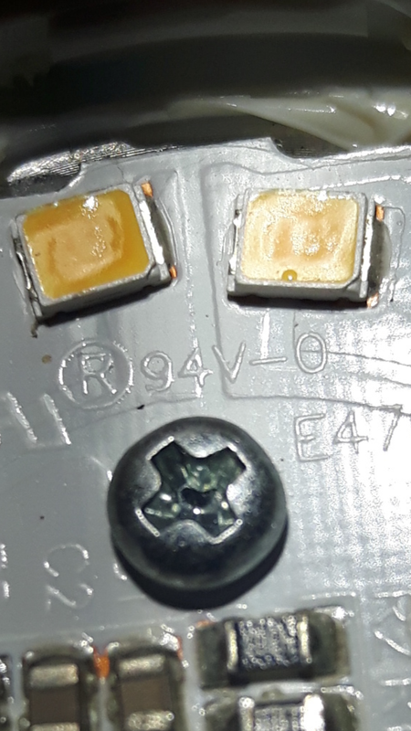
Earlier f-e commented that the 94V thing is a safety regulation number, and doesn’t necessarily mean they are 94V... I think. Again I default to him on this one haha.
 

PCBuds

Well-known member
View Image

What the heck.
Is the whole circuit running @ 94 V?

Apparently it's a circuit board classification.

94v-0 is a UL circuit board classification, regarding it's thermal characteristics.

If your 18 leds were in series, something like a 54v driver would be typical. The fancy pants driver onboard, takes the half wave voltage, and without smoothing, applies the voltage to the leds. As the voltage waveform rises, so does the current. The chip watches the voltage over a resistor to determine the current flowing. When the current so almost to great, the power is disconnected. The waveform carries on rising, peaks, drops, and the leds are again connected. This gives you about 60 flashes a second.

It doesn't look like the leds are all in series, so a fixed external supply won't be simply soldered on.


You're perhaps thinking, that 3 of the 54v $5 cobs could be run in series off your rectified mains. They could, but you would get a power spike one day that killed them. An improvement is to add current limitation, such as a simple switching regulator to pull the power as current rises too high. HGL just started using such a design, but it's very noisy in the radio spectrum. Lots of filters and protection are needed, and just like HGL, you probably wouldn't get it right. It's more effort than any other part of a lighting build. Requiring a lot of test and measurement gear. They simply didn't bother.

I'm not sure it's worth building drivers. The one's in our domestic lamps are fine. Meanwell are fine. Osram. Others... but not the $10 ebay stuff. They can get it right, but nearly always omit the filter stages in favour of cost saving.

By all means have a go, it's interesting in a rather geeky way. You won't improve upon the store version though. There is nothing wrong with it.
 

PCBuds

Well-known member
I’ve wondered this myself, but thinking about it logically I doubt it. I would think that the driver is designed for the LED board but I don’t have anything to back this up. Someone with better electronics info like f-e could tell us. However, on these bulbs where the driver is separate I think you could maybe power multiple boards using a single meanwell or similar driver instead. This would increase their efficiency and give you a little more control on how hard you drive them. We could probably talk PCBuds into trying it out haha!

I don't think the driver could power multiple circuits. And it would have to be a bulb where the driver was completely separate from the LED segments, with no circuits on the board.

This is the one I stuck in the water.


I'm going to try to put power to each LED segment and see if they are still working.

I'm thinking they're still good.
 

Hephaestus

Member
No, I didn't know that.

It sounds like a safer option.

https://www.homedepot.com/p/Lithonia-Lighting-4-ft-Fluorescent-Tube-Protector-TGT8CL4-R24/100163152

3.57$ price has gone up :)

We used to use them for a cheap source of harder larger OD clear tubing in aquarium projects all the time.

Sure beats trying to scrape out phosphor coatings - of that im 100% sure. And there's mercury in those lights. Dont risk heavy metal contamination.
 

PCBuds

Well-known member
Could one of those drivers pack enough punch to power multiple SIL circuits simultaneously?

A driver pack is designed to power just the LED segments either in series or parallel or a combination of both.

I suppose you could remove the circuits from one SIL and then tap into another SIL and use its driver but you'd have to solder each LED segment individually and that's too much effort even if just as a test.


PCBuds

Well-known member
https://www.homedepot.com/p/Lithonia-Lighting-4-ft-Fluorescent-Tube-Protector-TGT8CL4-R24/100163152

3.57$ price has gone up :)

We used to use them for a cheap source of harder larger OD clear tubing in aquarium projects all the time.

Sure beats trying to scrape out phosphor coatings - of that im 100% sure. And there's mercury in those lights. Dont risk heavy metal contamination.

Yeah, I held my breath then filled it with water and dumped it down the toilet.

It's too much effort and the whole thing can shatter.
 

PCBuds

Well-known member
I checked the individual LED segments and they are all working.


Then I looked at my Noma bulb and all the segments are in series.
It's a non-dimmable bulb and that may have something to do with it.

It seems like a more efficient design.

I managed to feed power to a few segments and they seem to need the same voltage as the other bulb to get them to lite.


Here's where the positive feeds in.


Here's the negative.


I'm going to try to feed straight AC into the 15 series LED segments by removing the LED's from the rest of the circuit.

I'm going to use a regular 120 V household dimmer so I can adjust the voltage but the dimmer says incandescent only and the bulb says non-dimmable.

I think it will work but now I'm playing with 120 V house current.

I don't mind blowing up the bulb but I don't want to blow myself up. Lol


PCBuds

Well-known member
It works !!


It didn't work with the dimmer. It could be how the dimmer is designed or the dimmer might be broken. (I think I got it at a garage sale)

So I just fed the 120 V straight into LEDs and it works fine.

I did notice the flashing and it doesn't have a rectifier circuit so it's only getting half the wave.

I'm thinking of a full-wave bridge rectifier circuit or maybe just a simple capacitor.
(But I'm not sure how to hook one up to AC)

Four diodes and a capacitor should stop the flashing.
 

PCBuds

Well-known member
I took the bulb apart some more and found a capacitor and that inline resistor.


I still don't understand what that resistor does?

It was mentioned that the voltage drop is monitored by the circuit so it can adjust the current but I would think that you would need a wire feeding from both sides of the resistor to measure the voltage?

I am questioning the value of my research but I suppose, I could gut the circuit board from maybe 6 identical bulbs then glue them to a cookie sheet, (with my special heat-conducting silicone), have them all wired in parallel and make a 120 V driver that would be outside the grow area so its heat isn't inside the grow.

The circuit boards won't have parts on the back so they could mount nicely to a heat sink.

You could manually overdrive them a bit but that might be hard to control without a current limiting power supply.

I'm sure I'd be better off just buying led strips and run them off an LED driver.

No great loss, just another $2 bulb.
 

PCBuds

Well-known member
Thank god you're finally ditching that 1975 shop-light monstrosity. :biggrin:


Looks like led gardener for the plans and parts list and digikey for the supplies.


Actually sounds like a cool project. :tiphat:

I've watched a couple of videos and I'm just about ready to make some purchases.
 

Hookahhead

Active member
Im pretty sure the resistor limits the flow of electrons to one direction. I believe this protects the circuitry... Ive seen this with solar panels so that they can only feed a battery and not drain it. I bet if you reverse the polarity (positive to negative and vise versa) the bulb won’t light up.
 

PCBuds

Well-known member
Im pretty sure the resistor limits the flow of electrons to one direction. I believe this protects the circuitry... Ive seen this with solar panels so that they can only feed a battery and not drain it. I bet if you reverse the polarity (positive to negative and vise versa) the bulb won’t light up.

I installed a little solar panel under the sunroof in my car and it's got a diode in it so power only goes into the battery but that thing on the SIL is a resistor and it only measures 0.09 ohms. (unless my ohmmeter isn't accurate at such a low resistance)

It's almost a dead short.
I suppose it is to limit current flow if the circuit fails but it's such a low resistance, it would easily blow your house fuse.

At first, I thought it was a "thermo time switch". Those things are like a fuse but instead of popping from too much current, they blow when they get too hot.

Either way, they heat up and waste electricity.
 

Latest posts

Latest posts

Top