What's new

Growroom Electricity and Wiring

overbudjet

Active member
Veteran
Hi Madpenguin would you please check these before i put power on
some electric


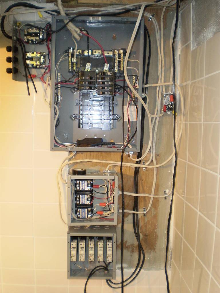
lower relay are for dehu. 2 x 15 amp 110v. 14/3
upper relay are for light 2 x 20 amp 220v. 10/2
controled by ssr (solid state relay)

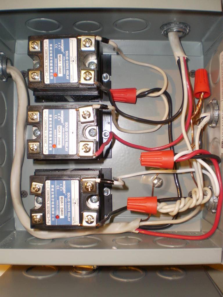
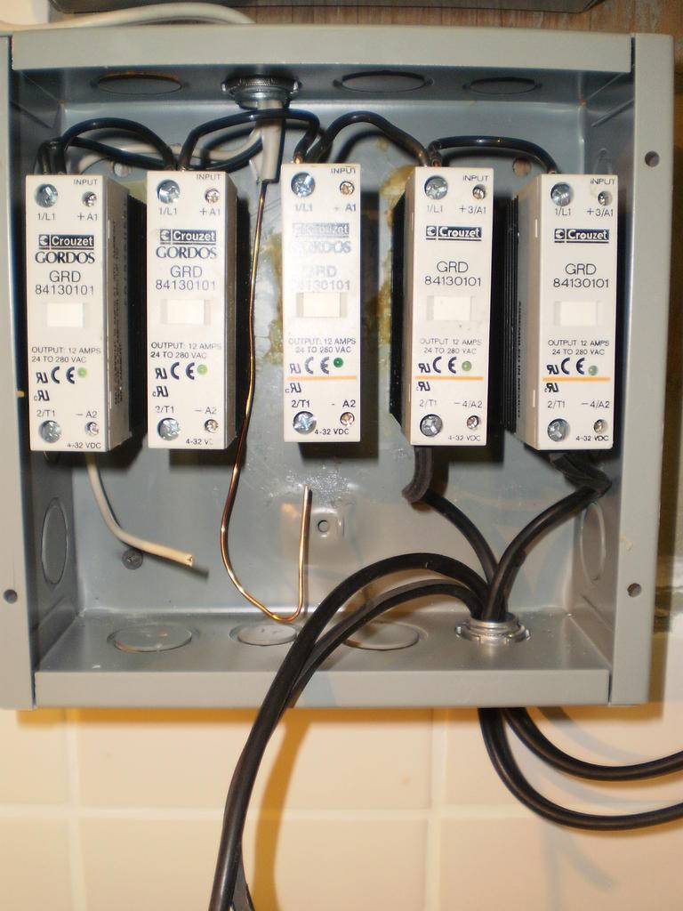
Switching box (ssr controled by computer)

upper box are for high power switching 12/3 2 x 15 amp
load look like this pump 7amp 110v. UC cooling (fridge) 5 amp 110v.Some fans 4 amp 110v.And 1 (not switched) 5 amp 110v.

lower box are for low power switching 14/2 1 x 15 amp
coil relay see first pic,heat exchanger,sulfer burner,selenoid valve,


__________________
 

GeorgeSmiley

Remembers
Veteran
All that's left is the relay and the 240v side :)

picture.php


5 hours
 

madpenguin

Member
@ overbudjet.....

It's really hard to tell what's going on. This is one of those things where I would be sticking my face right in a panel and moving wires around to trace them.

Example is your 2 power control relays. For one, your separate picture of it is upside down and cropped way too close. I have to look at my monitor upside down just to put it in perspective with your panel.....

I noticed your using 2 conductor ST-3 cord for the coil contacts on one of the power control relays. How is that industrial relay going to be triggered when you have 2 -120v lines of the same phase on the center contacts?

What is the coil voltage of those industrial relays?

Also looks like you need to ground that lower SSR box out. Could be missing a 3/4" - 1" NM connector up top for the panel feed.

Wait.... That ST-3 cord hooked up to the relay runs down the corner of the room and doesn't even hit those lower SSR's... I have no idea where that cord comes from/goes to....

The 2 ST-3 cords that do enter the SSR enclosure are just dangling up top by your power control relays... Atleast that's what it looks like to me...

Ugh... I can't make heads or tails of it with pictures. This is one of those things where I'd have to have my nose right up in it. There are so many wires in that Industrial relay box that I can't trace them with my eye....

Also, Your using at least 2 - 14/3's coming out of your panel.

The upper one goes to the enclosure with 3 relays. That should be on a DP breaker. So should the lower 14/3 in the panel but I'm not even entirely sure where that goes. Does it use the bottom of the panel as a chase and then run up to feed the lower industrial relay? If so, you have no load out conductors on that relay and I'm also not seeing a trigger wire for the center contacts...

It looks like your not even done wiring it..... Without further explanation from you, that's about all I can really say..... :frown:
 

madpenguin

Member
It's lookin' good George. Kinda wish I could zoom in on that.... :biggrin:

When you get your relays installed and hooked up, can you snap a few more?

You could probably fit at least 5 relays in that panel FYI. Lot's O' space...

Great idea to make a modular Power distribution board. Love the routed edges too. ;)
 

GeorgeSmiley

Remembers
Veteran
You can make them however long you want but the NEC requires that they atleast stick 3" out past the face of the box.

Wirenuts make an excellent connection when it comes to solid conductors. The only reason why I went the crimp route is because all my shit was stranded....

It looks like your using spec grade 15A receptacles. Keeping the end straight (if it's solid wire) and using the receptacle plates to screw down on the wire should be better than using spade connectors.

Yeah I finally ran into NEC 300.14 (6" from emergence 3 in past front edge)

I figured out it would be better to not use terminals on some connections about when I was finishing up :D I used my fluke and checked every ground, hot, neutral and everything is connected, properly grounded etc.


It's lookin' good George. Kinda wish I could zoom in on that.... :biggrin:

When you get your relays installed and hooked up, can you snap a few more?

You could probably fit at least 5 relays in that panel FYI. Lot's O' space...

Great idea to make a modular Power distribution board. Love the routed edges too. ;)

Thanks man, I'm waiting on more money to come through in 2 weeks so just in a hold pattern on the grow room. Trying to do it in big waves so I don't have to carry all the plants out of there.


I wish I would have ordered 2 relays at the same time..... they bone you on the shipping. I think when mine arrives I might take it to the supply house and see if they have one. I found these cord management things at the Elec supply house a few years ago and I finally found a use for them ;)

I think I'll grab a couple of 240v 20a duplex recep at the hydro store and put in a double box so I have 4 timed 240v but I'm beat.... lol. I just hate that they're friggin almond.

I bought a Klein Katapult stripper this morning because my brother swiped my old ones. Sure made the job nice. That ratchet crimper from harbor freight is the nuts. I really never buy cheap tools but this time I made an exception. It works just fine. The handles feel like shit and it's not ergonomic in any way shape of form but it was like $10 :D

picture.php


Just let me know if you want a shot or zoom of anything. I took lots of pictures.

Cheers
Smiley
 

madpenguin

Member
I wish I would have ordered 2 relays at the same time..... they bone you on the shipping.

Edited... I have a beef with Willy's Electronics and I don't feel like giving myself away on a public forum.

I would suggest people look elsewhere for their relays. Doing a markup on shipping is only one way they are unprofessional and don't deserve your business....

Buy from them if you must but you can order from Grangers and a whole host of other places. Also, Your local Electric Supply house will carry Contactors which are pretty much the same thing....
 

madpenguin

Member
Relays 101

Relays 101

Thought I would do a small tutorial/explanation about relays. I've gotten a few inquiries, so why not? BTW, this is all copied from elsewhere. Read it if you want or just skip to the pictures at the end... Up to you....
================================================

But first, A word from our sponsor.... Grainger Industrial Supply helps customers save time and money by providing them the right products to keep their facilities up and running. With more than 18,000 knowledgeable employees, the Grainger team works closely with customers to better understand their challenges and provide cost-saving solutions. Serving America since 1927.... "Grainger. For the ones who get it done."

All photos are courtesy of grainger.com and MadPenguin Inc. is in no way affiliated with Grainger, ( Just trying to steer people away from Willy's Electronic Discount Bargain Emporium)... The nice thing about Grainger is, they are freaking everywhere. I have one right down the street from me. Why I ordered online, I'll never know. Just make sure you call before you go in. Often times they need to order it from another store.

=================================================

"Electromechanical relays are perhaps the most widely used relays ..... today. They are made of a coil, an armature mechanism, and electrical contacts. When the coil is energized, the induced magnetic field moves the armature that opens or closes the contacts.

Electromechanical relays support a wide range of signal characteristics, from low voltage/current to high voltage/current and from DC to GHz frequencies. For this reason, you can almost always find an electromechanical relay with signal characteristics that match given system requirements. The drive circuitry in electromechanical relays is galvanically isolated from the relay contacts, and the contacts themselves are also isolated from one another. This isolation makes electromechanical relays an excellent choice for situations where galvanic isolation is required." (zone.ni.com/devzone/cda/tut/p/id/2774)

"Galvanic isolation is the principle of isolating functional sections of electric systems so that charge-carrying particles cannot move from one section to another, i.e. there is no electric current flowing directly from one section to the next." (wikipedia)

"The contacts on electromechanical relays tend to be larger and more robust than some other relay types. The larger contacts give them the ability to withstand unexpected surge currents caused by parasitic capacitances present in your circuit, cables, etc. An unfortunate tradeoff, however, is that the larger contacts require larger package sizes so they cannot be placed as densely on a switch module.

While the mechanical construction of electromechanical relays allows for much flexibility in switching capability, they have one important limitation: speed. When compared to other relays, electromechanical relays are relatively slow devices -- typical models can switch and settle in 5 to 15 ms. This operating speed may be too slow for some applications.

Electromechanical relays typically have shorter mechanical lifetimes than other types. Advances in technology have increased their mechanical lifetime but electromechanical relays still do not have as many possible actuations as a comparable reed relay. As with any relay, the amount of power being switched and other system considerations can have a significant impact on the overall lifetime of the relay. In fact, the mechanical lifetime of an electromechanical relay may be smaller than that of a reed relay, but its electrical lifetime under a similar load (particularly a capacitive load) might decrease at a much slower rate than that of a reed relay. The larger, more robust contacts of an electromechanical relay may often outlast a comparable reed relay.

Electromechanical relays are available in both latching and non-latching varieties. Non latching relays require continuous current flow through the coil to keep the relay actuated. These are often used in applications where the relay must switch back to a safe state in the event of a power failure. Latching relays use permanent magnets to hold the armature in its current position, even after the drive current is removed from the coil. For very low-voltage applications, latching relays are preferable because the lack of coil heating minimizes thermal electromotive force (EMF) which can affect your measurements." (zone.ni.com/devzone/cda/tut/p/id/2774)

=================================================

Here is a Single Pole Single Throw (SPST) Electromechanical Relay:
Relay, SPST-NO-DM, 4 Pins, 120VAC


picture.php


(BTW, Smiley, the above is the proper relay to use inline with your timer for the 120v side of your Distribution board.) There is only one "pole". It consists of the right hand metal arm and the left hand metal arm. Back some in the middle of the relay you can see one of the coil screw contacts. There is another one on the other side in the same position. This SPST relay is in a Normally Open (NO) position, meaning that when there is no electricity supplied to the center contacts, the top armature is raised and therefore does not complete the path from right contact to left contact. Once you apply current (a very nominal amount in the milliamp range) to the center contacts, the armature is magnetically energized and "snaps" down to meet both the left and right hand "arms", thus completing the circuit.

Notice the coil voltage imprinted in the lower right hand side of the relay. It says 12VDC. We want to use either 120VAC or 240VAC, depending on what we have going on. If we had a 120v coil relay, we would need a hot on one screw and then a neutral on the other side screw, thus completing the circuit and closing the armature.

Our "Always Hot" wire would be terminated to either screw. We can call this our "line in". On the other screw, you would attach the hot wire that will be feeding a 120v load. We can call that the "load out". We are feeding 120v because we only have one wire and here in N America, we have 120v on one wire.....

NOTE: Never, ever, ever, ever switch a neutral conductor.

The NEC expressly forbids the switching of grounded conductors (a neutral). There is one exception and it's a no-brainer. You must also simultaneously disconnect ALL ungrounded conductors (hot wires) at the same time. That's somewhere in the beginning of Article 400 if I'm not mistaken.

I say it's bad form regardless. I'm not knocking any one or any certain company that may be floating around but when making flips, you should only attach your ungrounded conductors to the relay and securely wirenut or by some other means create a permanent/semi-permanent bond between all grounded conductors (neutrals).

I had a brief thought about using a DPDT relay to make a 120v 1 ballast flip box but then changed my mind. Instead, that relay would be ideal for a 2 ballast flip box @ 120v. I would probably even wire it as a MWBC so the neutral would see minimal return current. And again.... With a MWBC, make sure those neutrals NEVER come loose or your going to fry some expensive 120v equipment...

Onwards..... Since I just touched on a Double Pole Double Throw (DPDT) relay, let's have at it.
Relay, DPDT, 8 Pins, 120VAC
Relay, DPDT, 8 Pins, 240VAC


picture.php


continuing tutorial in stages....
 

madpenguin

Member
You already said it on your thread.... ;)

What ever the voltage your timer operates on.....

They have the dial/peg crappy timers at some hydro stores that are 240v so you can use them with 240v ballasts. If you have a crap load of lights, just use one of those 240v timers to control a 240v DP relay.....

Obviously, in that case, you would have a red L1 on one coil contact and a black L2 on the other coil contact.

But all that will be added to the relay tutorial tomorrow. I'm getting screen burn from being online so much today.... :blowbubbles:
 

GeorgeSmiley

Remembers
Veteran
Sorry but as soon as I posted that, in my thread, I regretting giving advice that I was only 70% sure :D :D :D

So I thought I would mention it here, then I saw the relay tutorial.... hey man I'm a stoner


:laughing: :joint: :smokeit: :canabis:
 

madpenguin

Member
Yea, the 12v coil contacts are used widely in automotive applications, obviously because of the 12v nominal battery under the hood.

Actually, your starter solenoid is nothing but a relay with the ignition wires acting as the coil contacts. The feed is the battery and the load is the actual starter motor....
 

Avenger

Well-known member
Veteran
I say it's bad form regardless. I'm not knocking any one or any certain company that may be floating around but when making flips, you should only attach your ungrounded conductors to the relay and securely wirenut or by some other means create a permanent/semi-permanent bond between all grounded conductors (neutrals).


I know you understand this, but I think you should qualify this statement by saying something about this exclusively pertaining to flipflops on ballasts supplied with 120 volts.

And if you are switching the ungrounded, then it is acceptable to simultaneously switch the neutral(grounded conductor) in a flipflop.

NEC said:
410.81 Switched Lampholders. Switched lampholders shall be of such
construction that the switching mechanism interrupts the electrical connection
to the center contact. The switching mechanism shall also be permitted to
interrupt the electrical connection to the screw shell if the connection to the
center contact is simultaneously interrupted.
 

madpenguin

Member
Shall be permitted........ I still say why do it? Especially if it's not "shall be required".

Ballasts are non-linear loads and you can get some freaky resonance on the neutral depending how many lights your trying to run on one circuit. Throw switching into the fray and it doesn't sit well with me. You also get a spike current and I don't see the point in impeeding the return path in any way shape or form. It's certainly not safer to break the neutral along with the hot. If anything, it's quite the opposite.

The only time I'll break a neutral is on a separately derived system like a generator or fire pump. I just don't see it happening on a 120 flip.

:2cents:

Now, that certainly doesn't mean you can't do it. The NEC allows for it and I'm not really implying it's unsafe either. I just don't see any benefit in it but yet see "potential" harm in doing so.

If I were to build a 1 ballast 120v flip, I'd use a SPDT....
 

Avenger

Well-known member
Veteran
What spike current are you refering to?


My concern with the manufactured flipflop units that only switch one of the leads(lamp center pin connection) from the ballast is that many times people are going to be using these units with ballasts that are powered by 240 volts.

So making and selling a one size fits all flipflop that only switches the one lead(lamp center pin connection) from the ballast is bad form to say the very least.

For a flipflop that will only be used on a ballast supplied with 120 volts, the fliflop that only switches the one lead(lamp center pin connection ) from the ballast is perfect.

This is a fine detail, that seems is very hard to get across.


I have much respect for your strict adhearance to the NEC code.
 

madpenguin

Member
What spike current are you refering to?


My concern with the manufactured flipflop units that only switch one of the leads(lamp center pin connection) from the ballast is that many times people are going to be using these units with ballasts that are powered by 240 volts.

I was referring to the spike current normally associated with core&coil ballasts... That's probably a moot point anyway.

I'm not sure I understand you tho. What does that have to do with anything. It doesn't matter what your primary side runs at, the secondary side will always output the same voltage.

So making and selling a one size fits all flipflop that only switches the one lead(lamp center pin connection) from the ballast is bad form to say the very least.
Edit... I'll agree. If the socket shell is not at ground potential, then it should be switched. This all boils down to people doing as you say, a "one size fits all" type setup.

For a flipflop that will only be used on a ballast supplied with 120 volts, the fliflop that only switches the one lead(lamp center pin connection ) from the ballast is perfect.

Doesn't matter what the primary side of the ballast uses, the "bulb" will always receive the same output.
This all boils down to making a flip that tries to be universal and it allows the user to plug a 120v cord into a 240v receptacle is completely moronic on the part of the manufacturer. Someone here in this thread did the very same thing and fried his 120v ballast because he plugged it into a controller or flip box and the receptacle was outputting 240.

You should never be allowed to plug a 120 plug into a 240 receptacle. That's why they make different NEMA configurations and if a company is wiring their flip or controller up so a 5-15R or a 5-20R is receiving 240v, then they have no business making products in the first place IMO....
 

Avenger

Well-known member
Veteran
I was referring to the spike current normally associated with core&coil ballasts... That's probably a moot point anyway

Yes, moot point because a flipflop relay does not interupt power to the ballast.

I'm not sure I understand you tho. What does that have to do with anything. It doesn't matter what your primary side runs at, the secondary side will always output the same voltage.

It matters because if the ballast is supplied with 240 volts then the screw shell connection is not at ground potential and as you said...

If the socket shell is not at ground potential, then it should be switched.


"This all boils down to people doing as you say, a "one size fits all" type setup."


Yes!!! Thank you!!

Because a commercially made flipflop unit can be used on a ballast with any number of voltages supplied(120v, 240v, 277v, even 480v) it should be made to meet code no matter which voltage supply the end user has.


Doesn't matter what the primary side of the ballast uses, the "bulb" will always receive the same output.
This all boils down to making a flip that tries to be universal and it allows the user to plug a 120v cord into a 240v receptacle is completely moronic on the part of the manufacturer. Someone here in this thread did the very same thing and fried his 120v ballast because he plugged it into a controller or flip box and the receptacle was outputting 240.

You see thats the thing. The lamp cord that runs from the ballast to the bulb is not voltage specific. There are a couple proprietary plugs used, but they use the same plug for the lamp cord no matter what voltage is supplied to the ballast.

I was telling DB2004(nowirenuts) just the other day that his use of nema 5-15 recepticles and plugs on his flipflop lamp cord connections was not only under rated for the open circuit voltage, but that it leaves it possible for some idiot to plug his occilating fan in there. :jump:


Anyway bro, keep up the excellent work and thanks for hearing me out.
 

madpenguin

Member
It matters because if the ballast is supplied with 240 volts then the screw shell connection is not at ground potential and as you said...

You know, for some reason now, I'm doubting whether you would ever read a voltage potential of 0 between the socket shell and ground even when the primary is at 120. Xfmr's really aren't my thing but I seem to remember something from my apprentice days on this.

I loaned my 600v multimeter out and never got it back but as soon as I buy a new one, I'll take a reading at my 120v fired sockets. If there is even a reading of 5 volts between ground, then I fucked up with saying you shouldn't be switching the neutral.

:peek:
 

Avenger

Well-known member
Veteran
retract all that. I had my primary wiring reversed. ack!


0 volts screw shell to ground on a CWA ballast supplied with 120 volts.
 

GeorgeSmiley

Remembers
Veteran
So did i wire this correctly? Your walk-through mentioned 240v breifly but I wasn't quite sure. Want to BE sure before I mount this thing.

picture.php


I think i may end up wanting the veg lights 240v and also keep some timed 120 on the same timer. So i would only need another relay like this and then 6-20r's. Looks like I can fit another relay in there for a flip flop if the need arises.

Cheers
smiley
 
Top