
I have another question for the electrical gurus. Rives I like to think this thread is a source of entertainment for you. Hopefully the endless question amuse you and pass some time.
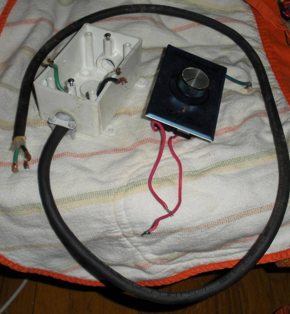
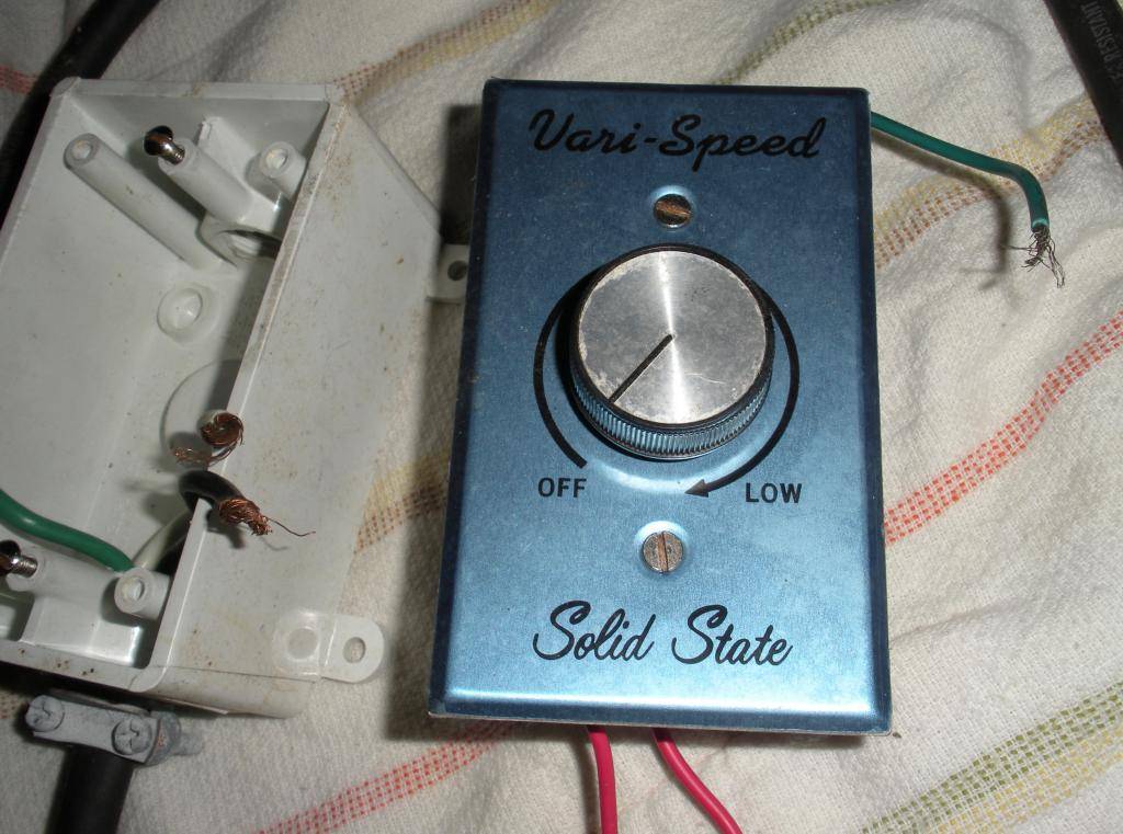
I have a 6" 400 cfm centrifugal duct fan drawing in outside air from a 6" vent tubing. The fan has a 3 prong plug. I need to install a fan speed control. I was just going to buy one but then I remembered I had this unused but a few yeas old Vari-Speed control.
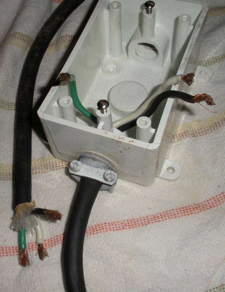
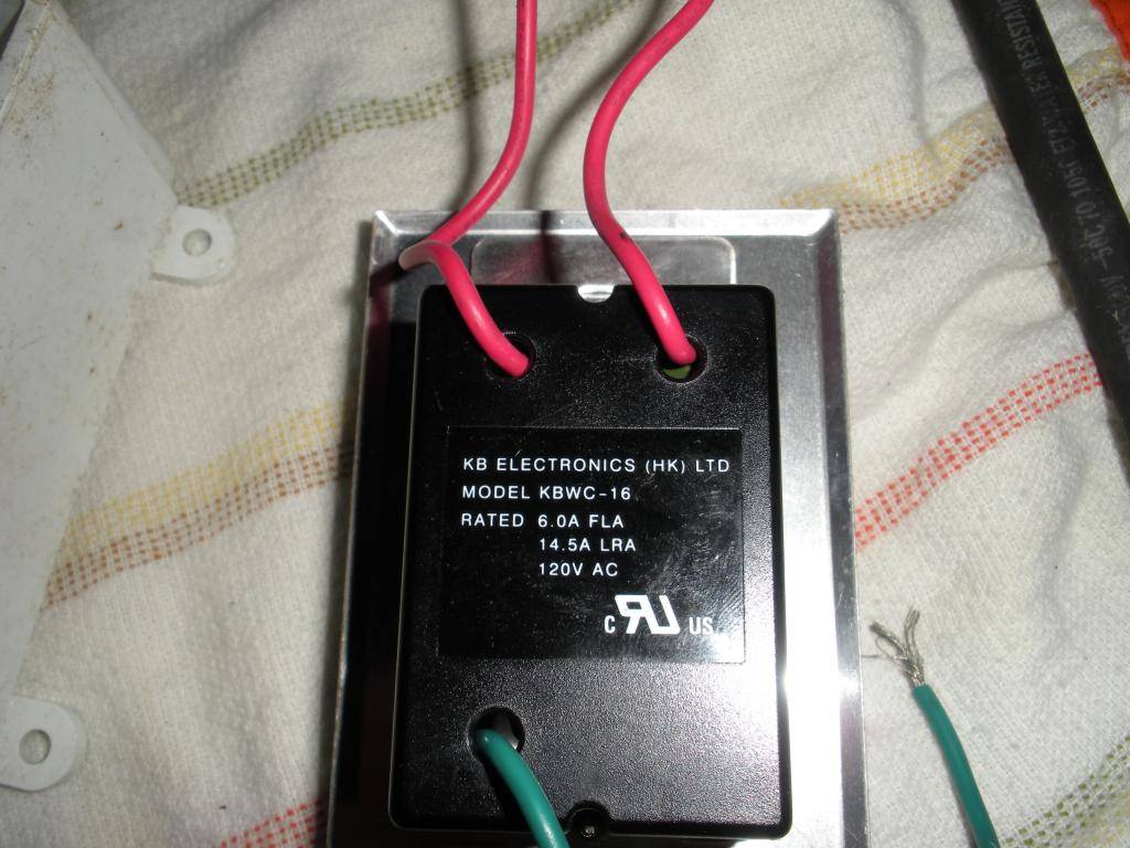
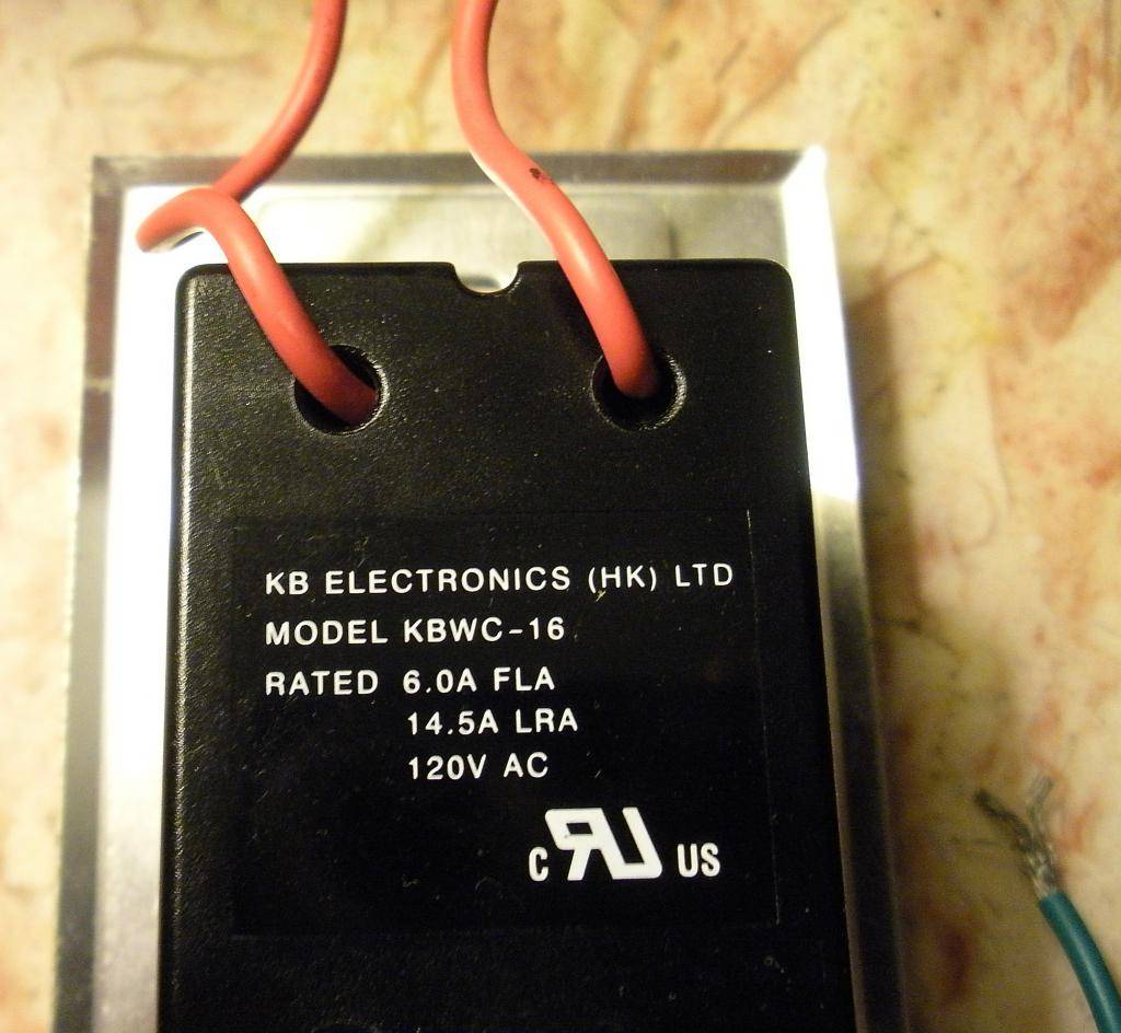
I scavenged a plug cord from it but don't remember how it goes together. It has 2 red wires and one green one. Which red is power and which is neutral. I assume the green is ground.
I want to be able to plug the timer into the outlet and the fan into this speed control.
What do I need to get and do? I guess I need a male 3 prong plug connected to some 3 wire and a 3 prong female outlet and 3 wire.
Here are the pics of what I have.
I have a 6" 400 cfm centrifugal duct fan drawing in outside air from a 6" vent tubing. The fan has a 3 prong plug. I need to install a fan speed control. I was just going to buy one but then I remembered I had this unused but a few yeas old Vari-Speed control.
I scavenged a plug cord from it but don't remember how it goes together. It has 2 red wires and one green one. Which red is power and which is neutral. I assume the green is ground.
I want to be able to plug the timer into the outlet and the fan into this speed control.
What do I need to get and do? I guess I need a male 3 prong plug connected to some 3 wire and a 3 prong female outlet and 3 wire.
Here are the pics of what I have.
")

