
-
Happy Birthday ICMag! Been 20 years since Gypsy Nirvana created the forum! We are celebrating with a 4/20 Giveaway and by launching a new Patreon tier called "420club". You can read more here.
-
Important notice: ICMag's T.O.U. has been updated. Please review it here. For your convenience, it is also available in the main forum menu, under 'Quick Links"!
You are using an out of date browser. It may not display this or other websites correctly.
You should upgrade or use an alternative browser.
You should upgrade or use an alternative browser.
Application of Nano PLC In A Growroom
- Thread starter imnotcrazy
- Start date
D.I.Y. Ballast Flip-Flop Assembly Part 1
D.I.Y. Ballast Flip-Flop Assembly Part 1
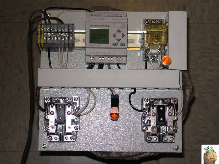
Alright, I have finished the control layout, wiring and PLC programming. So here it is.
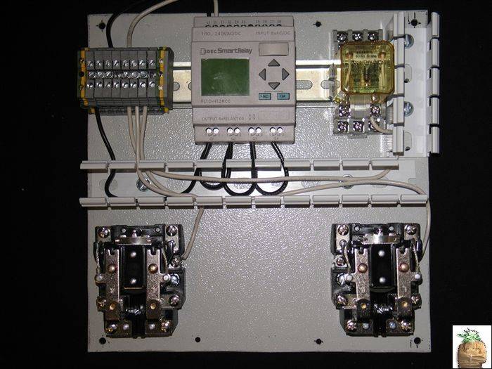
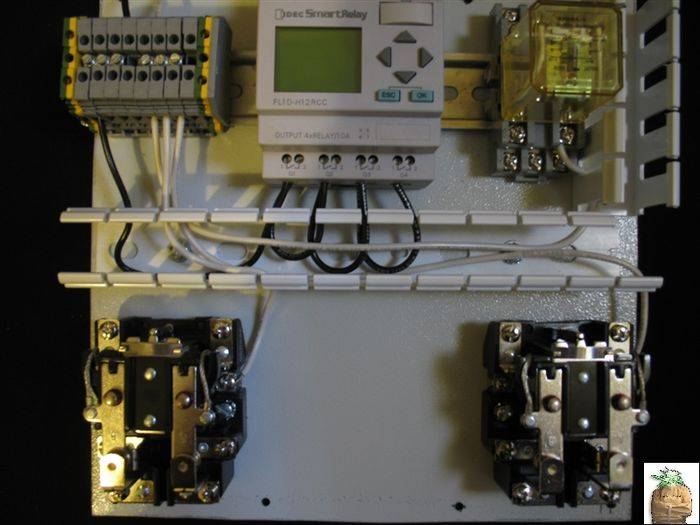
So, following the above rules for YOUR material list we layout the panel (yours may look very different, as long as it is wired the same it WILL WORK):


Now that we have a layout and everything is secured to the panel, we wire the 24/7 120Vac Hot leg. If you look closely, all of these terminations are tied common to each other ( to be tied to a male plug for supply power):
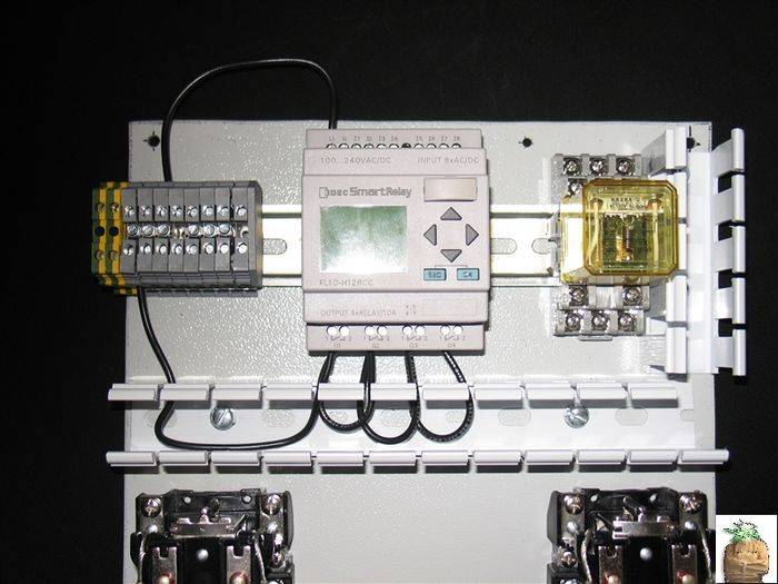
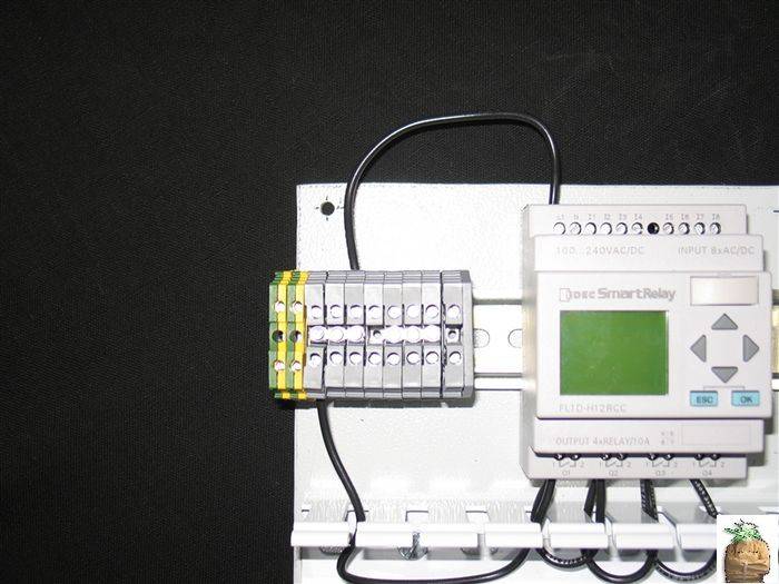
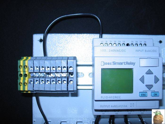
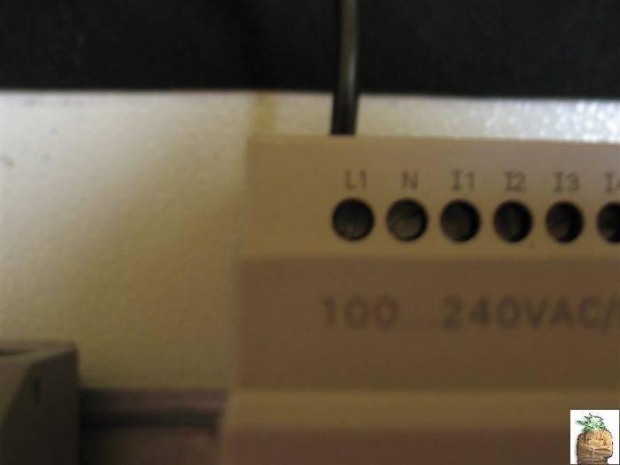
Followed by the Neutral (or 2nd Hot leg if you choose to use 220Vac control power). These are tied common to one another, same as the Hot line:


D.I.Y. Ballast Flip-Flop Assembly Part 1
Alright, I have finished the control layout, wiring and PLC programming. So here it is.
So, following the above rules for YOUR material list we layout the panel (yours may look very different, as long as it is wired the same it WILL WORK):
Now that we have a layout and everything is secured to the panel, we wire the 24/7 120Vac Hot leg. If you look closely, all of these terminations are tied common to each other ( to be tied to a male plug for supply power):
Followed by the Neutral (or 2nd Hot leg if you choose to use 220Vac control power). These are tied common to one another, same as the Hot line:
Last edited:
D.I.Y. Ballast Flip-Flop Assembly Part 2
D.I.Y. Ballast Flip-Flop Assembly Part 2
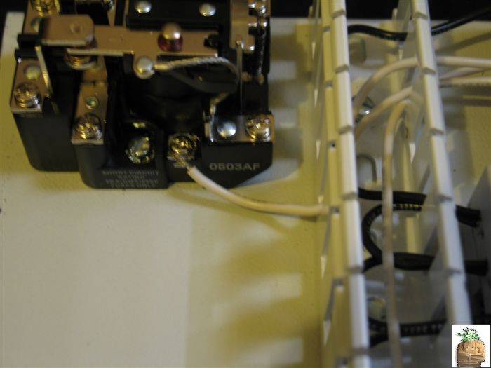
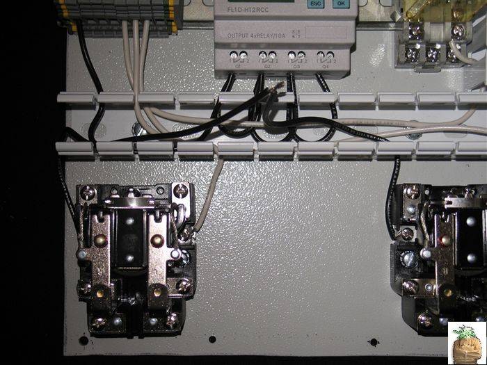
OK, Now that we can supply power to the circuit, we have to wire all the Relays/Contactors into the circuit for proper operation:
We already tied in the Common/ 2nd Hot line to the B side of the Relay/Contactor Coils in step #1. Now, we have to tie them into the P.L.C. outputs so the program we install will function properly.
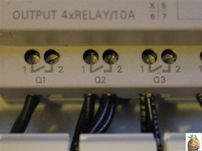
The outputs are designated as Q# (# pertaining to input address, similar to PC network structure), so we'll label Q1 : Ballast Power Control and tie it to the Ballast Power Relay (BPR) and label Q2-X : Lamp/Room Selection Control and tie it to the Lamp/Room Selection Relays (LSRs). ( I only need Q1 in MY project because I do not need my room to power up in stages. You can do this easily using the other inputs. And I'll explain how. )
We'll start with wiring Q1 to the BSRs, which we've already supplied one side of the contact with 120Vac power in Step#1:
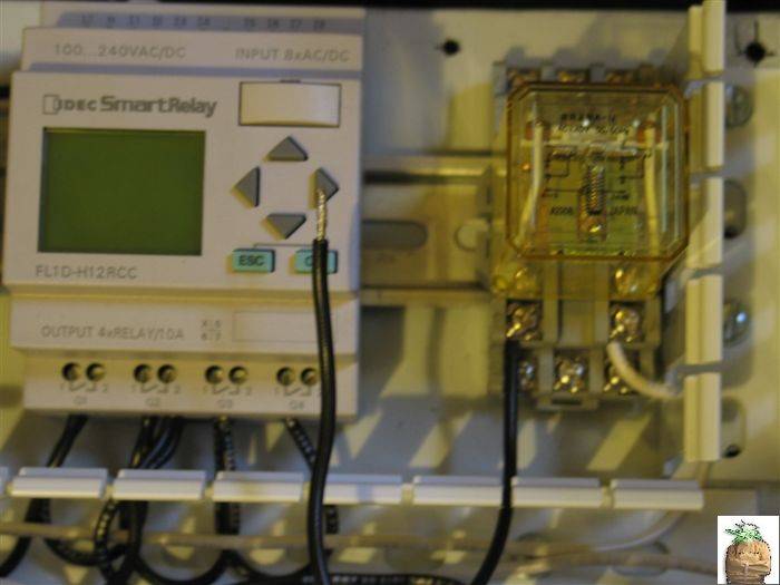
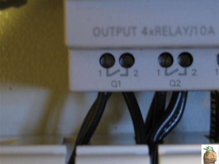
Next is to wire Q2 to the LSRs. Again, power was supplied to these contacts in Step#1:

OK, now everything is properly wired. We can now apply power. Remember how I mentioned how all the control power Hot lines were tied together? And how the Neutrals were also tied together?
I used terminal strips from work with 2 jumper bars (One for Hot lines, One for Neutral lines ) but, you can use wire nuts or another suitable method to tie them to a plug to supply power to the control circuit for programming. Here's my test plug in place for programming (Brown Wire ). :
As you can see, I have wired in 2 120Vac bulbs on the 2 relay outputs so I can take a sequence of pictures to show how it all works after programming; Which we are now ready for, we just have to plug in our plug which we just temporarily wired into place.
Here is a picture after initial Start-Up:
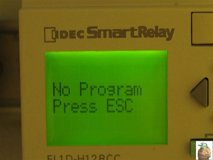
And after you press ESC:
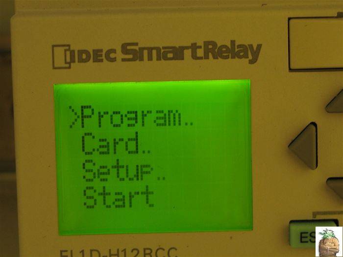
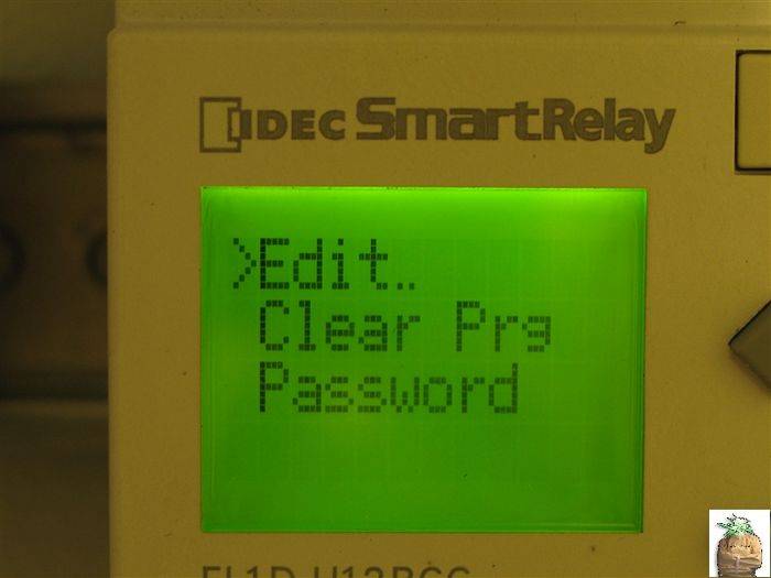
Now we have to enter the Program Editor which we do by pressing OK which brings up this screen:
Programming is our next step
D.I.Y. Ballast Flip-Flop Assembly Part 2
OK, Now that we can supply power to the circuit, we have to wire all the Relays/Contactors into the circuit for proper operation:
We already tied in the Common/ 2nd Hot line to the B side of the Relay/Contactor Coils in step #1. Now, we have to tie them into the P.L.C. outputs so the program we install will function properly.
The outputs are designated as Q# (# pertaining to input address, similar to PC network structure), so we'll label Q1 : Ballast Power Control and tie it to the Ballast Power Relay (BPR) and label Q2-X : Lamp/Room Selection Control and tie it to the Lamp/Room Selection Relays (LSRs). ( I only need Q1 in MY project because I do not need my room to power up in stages. You can do this easily using the other inputs. And I'll explain how. )
We'll start with wiring Q1 to the BSRs, which we've already supplied one side of the contact with 120Vac power in Step#1:
Next is to wire Q2 to the LSRs. Again, power was supplied to these contacts in Step#1:
OK, now everything is properly wired. We can now apply power. Remember how I mentioned how all the control power Hot lines were tied together? And how the Neutrals were also tied together?
I used terminal strips from work with 2 jumper bars (One for Hot lines, One for Neutral lines ) but, you can use wire nuts or another suitable method to tie them to a plug to supply power to the control circuit for programming. Here's my test plug in place for programming (Brown Wire ). :
As you can see, I have wired in 2 120Vac bulbs on the 2 relay outputs so I can take a sequence of pictures to show how it all works after programming; Which we are now ready for, we just have to plug in our plug which we just temporarily wired into place.
Here is a picture after initial Start-Up:
And after you press ESC:
Now we have to enter the Program Editor which we do by pressing OK which brings up this screen:
Programming is our next step
Last edited:
D.I.Y. Ballast Flip-Flop Programming Part 1
D.I.Y. Ballast Flip-Flop Programming Part 1
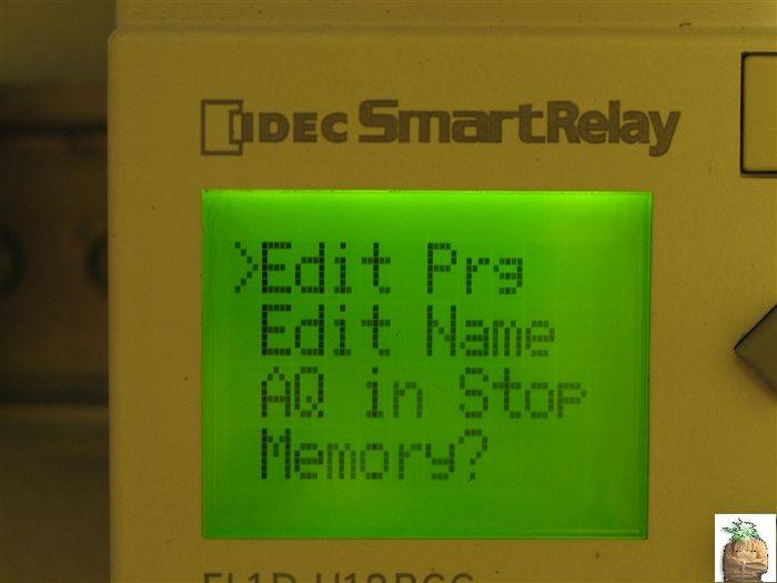
So we've powered up and walked through the menu structure to the Program Editor. Another Press of OK bring up the actual Program which is displayed like this ( Take Note: The programming structure of these units is such that you MUST work from OUTPUT to INPUT ) :

The Programming of these are similar to Boolean Logic (if you are familiar with computer architecture) with other modified functions added. Everything in our program will be either OFF/0/lo or ON/1/hi because this program does not deal with any Analog Signals....
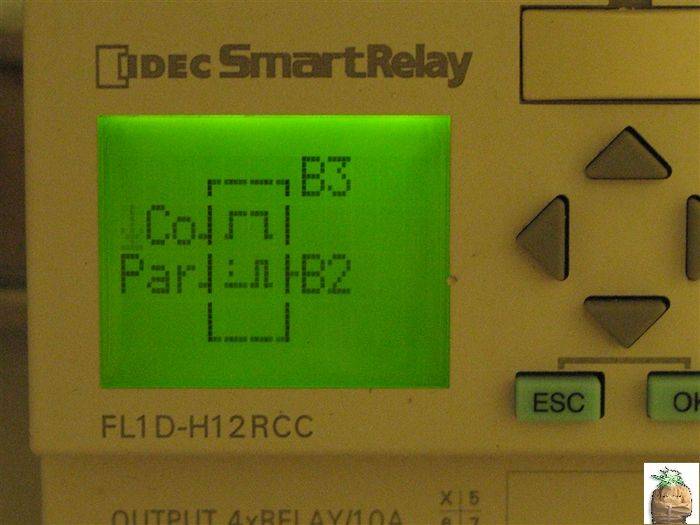
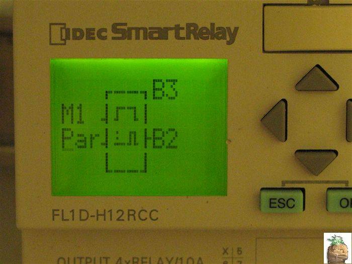
Press OK and, using the Right Button Change Q1 to display M1 like this:
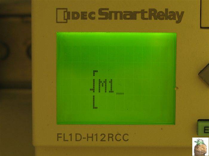
( In the Program Structure M# represents a Virtual Output in the program. Basically what this does is allow us to be able to have a step of the program be on or off. We can then utilize this M# somewhere else in the program structure later on. )
Press OK and using the Up/Down Arrows select SF for the Special Function Menu:

Pressing OK will bring you to the Special Function Menu. Using the Up/Down Arrows, select the Seven-Day Time Clock Function which looks like this:

Then Press OK TWO times. Once to select the time clock function and the second time to select the first "Timer Cam Switch" of the Time Clock. The Blank Timer Cam Setup Screen looks like this:
We now have to fill it in with the 7 days of the week and the times when you want the Flip Flop to switch from Room/Lamp#1 to Room/Lamp#2. Using the Up/Down and Left/Right Arrow Keys we fill it in like this:

In my example I have my selected switching times set at On: 18:00 (6 P.M.) and Off: 6:00 (6 A.M) you can choose any 12 hour period you would like but you have to adhere to the 24 hour ( 12:00 A. M. (= 00:00) - 11:59P.M. (=23:59) time structure of the P.L.C.
Pressing OK brings you back to the Timer Function main screen so you can set up the 2nd and 3rd timer "cams" (which we don't need to do for a Flip Flop). From here, scroll back to the M1 Bracket using the Right Arrow. Then, using the Right Arrow again, Change the M1 to Q1. It should look like this:
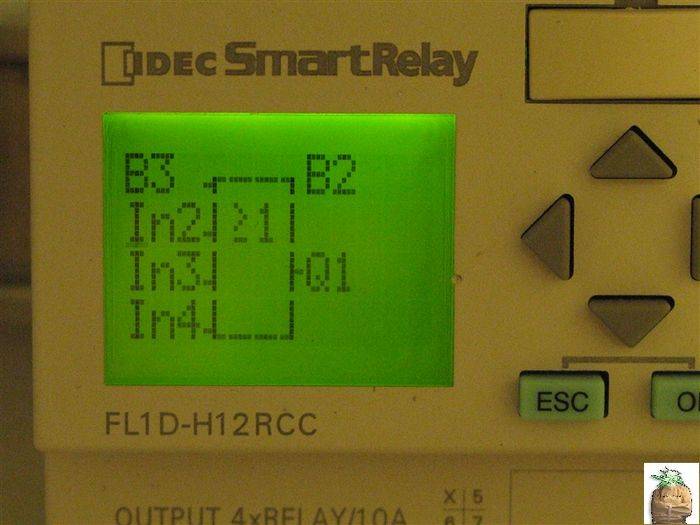
Here, we now begin programming the actual output to be able to fire the Q1Output. Press OK, then using the Up/Down Arrow keys Select the General Function Menu which looks like this:
Press OK and use the Up/Down Arrows to select an OR Gate which looks like this:
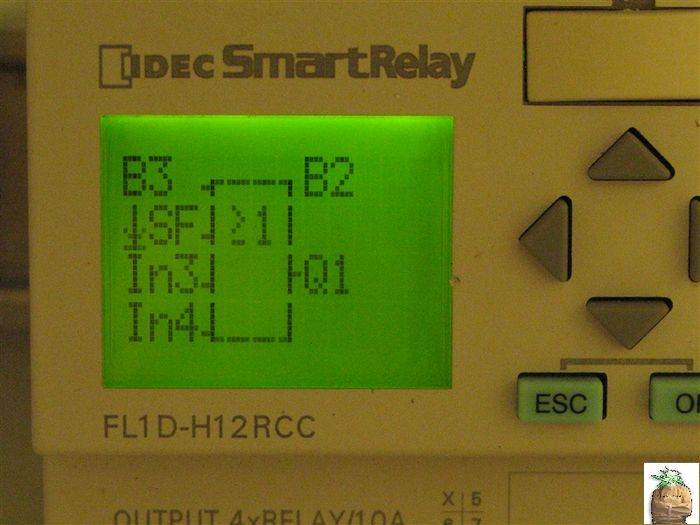
Now, scroll to the In1 Block on the top left. Pressing OK allows you to again select the Special Function Menu:

Press OK and bring up the Special Function Menu. The first Special Function is the ON-Delay Timer:

Press OK again. Now Select Co:
Now, remember the M1 Virtual Output we programmed earlier? Here's when we start to put it to use.
Press OK and scroll Up/Down. Using OK to select M1:
Your cursor should now be on the Par symbol. This represents the actual parameter set for the On-Delay Timer:

Scroll through and set the amount of time you want power to the ballast to turn off while the Lamp Switching will occur:

Here you can see, I chose 20 seconds as my delay for the LSRs to pull in. I may need to allow more time for the Soft Start Function of the Ballast to reset. I'm not sure if 20s will be suitable, but all of the Function Parameters are easily accessible later on after programming.
EDIT: With some trial and error, I have come to the conclusion the 20 second timers should be EXTENDED out to 2 minutes or longer (I am currently using 5 minutes for my dwell time) to allow the ballast to cool a bit and allow the ballast capacitor time to discharge. When I used 20 sec, the magnetic ballast didn't always fire AND upon consultation with other digital ballast users who have said you DO NOT want to drop/reapply ballast power rapidly as it can cause a digital ballast to FAIL and we wouldn't want that.
Press OK One more time to return to the ON-Delay Timer Main Screen
D.I.Y. Ballast Flip-Flop Programming Part 1
So we've powered up and walked through the menu structure to the Program Editor. Another Press of OK bring up the actual Program which is displayed like this ( Take Note: The programming structure of these units is such that you MUST work from OUTPUT to INPUT ) :
The Programming of these are similar to Boolean Logic (if you are familiar with computer architecture) with other modified functions added. Everything in our program will be either OFF/0/lo or ON/1/hi because this program does not deal with any Analog Signals....
Press OK and, using the Right Button Change Q1 to display M1 like this:
( In the Program Structure M# represents a Virtual Output in the program. Basically what this does is allow us to be able to have a step of the program be on or off. We can then utilize this M# somewhere else in the program structure later on. )
Press OK and using the Up/Down Arrows select SF for the Special Function Menu:
Pressing OK will bring you to the Special Function Menu. Using the Up/Down Arrows, select the Seven-Day Time Clock Function which looks like this:
Then Press OK TWO times. Once to select the time clock function and the second time to select the first "Timer Cam Switch" of the Time Clock. The Blank Timer Cam Setup Screen looks like this:
We now have to fill it in with the 7 days of the week and the times when you want the Flip Flop to switch from Room/Lamp#1 to Room/Lamp#2. Using the Up/Down and Left/Right Arrow Keys we fill it in like this:
In my example I have my selected switching times set at On: 18:00 (6 P.M.) and Off: 6:00 (6 A.M) you can choose any 12 hour period you would like but you have to adhere to the 24 hour ( 12:00 A. M. (= 00:00) - 11:59P.M. (=23:59) time structure of the P.L.C.
Pressing OK brings you back to the Timer Function main screen so you can set up the 2nd and 3rd timer "cams" (which we don't need to do for a Flip Flop). From here, scroll back to the M1 Bracket using the Right Arrow. Then, using the Right Arrow again, Change the M1 to Q1. It should look like this:
Here, we now begin programming the actual output to be able to fire the Q1Output. Press OK, then using the Up/Down Arrow keys Select the General Function Menu which looks like this:
Press OK and use the Up/Down Arrows to select an OR Gate which looks like this:
Now, scroll to the In1 Block on the top left. Pressing OK allows you to again select the Special Function Menu:
Press OK and bring up the Special Function Menu. The first Special Function is the ON-Delay Timer:
Press OK again. Now Select Co:
Now, remember the M1 Virtual Output we programmed earlier? Here's when we start to put it to use.
Press OK and scroll Up/Down. Using OK to select M1:
Your cursor should now be on the Par symbol. This represents the actual parameter set for the On-Delay Timer:
Scroll through and set the amount of time you want power to the ballast to turn off while the Lamp Switching will occur:
Here you can see, I chose 20 seconds as my delay for the LSRs to pull in. I may need to allow more time for the Soft Start Function of the Ballast to reset. I'm not sure if 20s will be suitable, but all of the Function Parameters are easily accessible later on after programming.
EDIT: With some trial and error, I have come to the conclusion the 20 second timers should be EXTENDED out to 2 minutes or longer (I am currently using 5 minutes for my dwell time) to allow the ballast to cool a bit and allow the ballast capacitor time to discharge. When I used 20 sec, the magnetic ballast didn't always fire AND upon consultation with other digital ballast users who have said you DO NOT want to drop/reapply ballast power rapidly as it can cause a digital ballast to FAIL and we wouldn't want that.
Press OK One more time to return to the ON-Delay Timer Main Screen
Last edited:
D.I.Y. Ballast Flip-Flop Programming Part 2
D.I.Y. Ballast Flip-Flop Programming Part 2
Now, we have provided a statement that will Power the Ballast for the HALF of a 24 hour period when M1 is activated by the 7-Day Timer. We need to now go back to the OR Gate of this line of the program and write the second half of the Ballast Power Code.
Press the Right Arrow THREE times to return to this screen:
Highlight In2 with your cursor and scroll to the Special Function menu:
Press OK and the first selection is the ON-Delay Timer again:

Now we have to make the On-Delay to work opposite of the first half of this "rung" of the program. Select the General Function Menu:

In the General Function Menu, select the NOT Gate using the OK button:
Now we Re-Use the M1 Virtual Output under the Co Menu ( which I forgot to get the picture of ):

And, Remember to go back and set the amount of time delay under the Par menu of the On-Delay Timer:

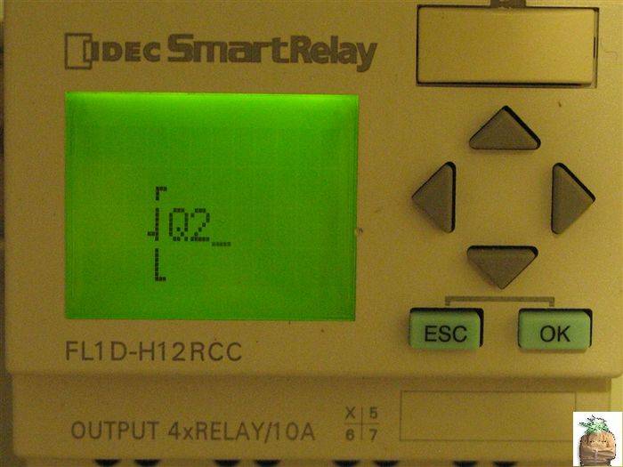
Return to the Q1 bracket at the beginning of this rung because it is now complete. Now, we can program for the LSRs to function properly. Change the Q1 to Q2:
And select the Special Function menu again:
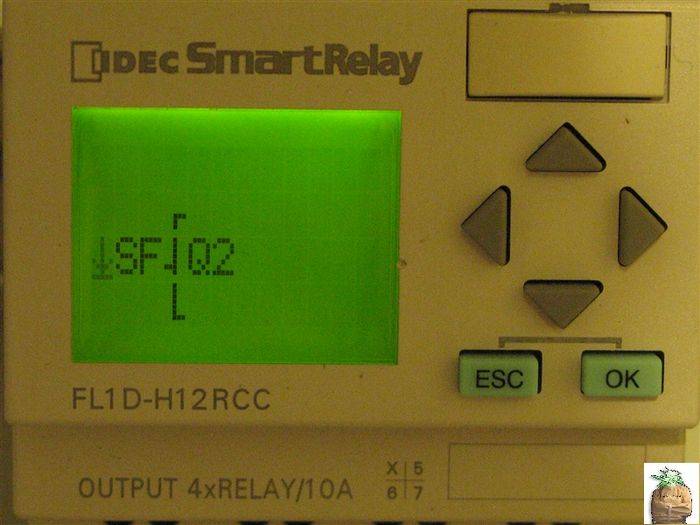
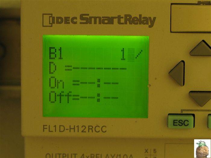
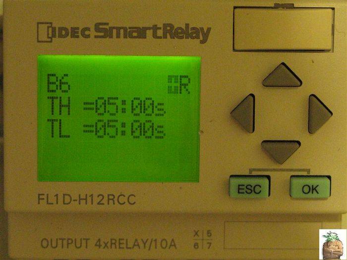
Press OK and scroll through this menu to the ON-OFF Delay Timer:
(This function will ensure that the contacts are ALWAYS closed before the ballast fires)
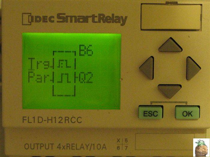
Select Co in the Timer's Menu:

And make M1 the trigger for the On-Off Delay Timer:

Enter the On-Off Delay Timer Parameter Menu:

And set a suitable ON and OFF times that will cause contact closure during the BPR(s) OFF cycle:
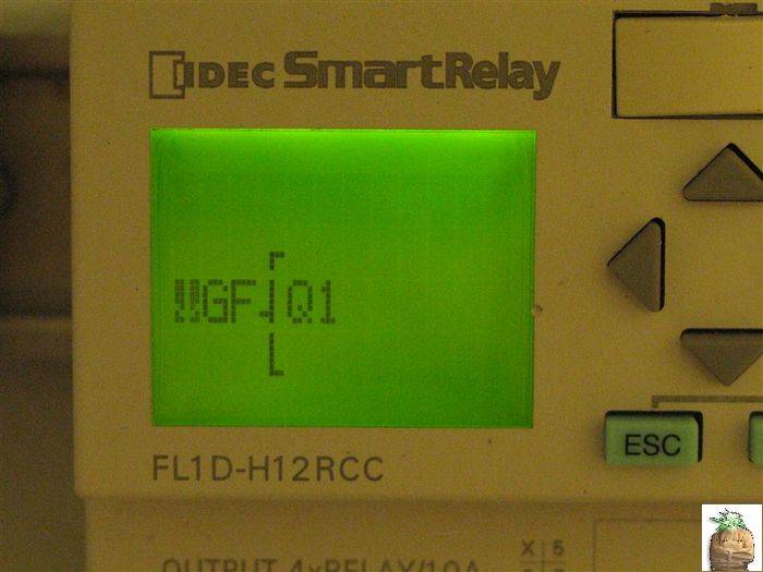
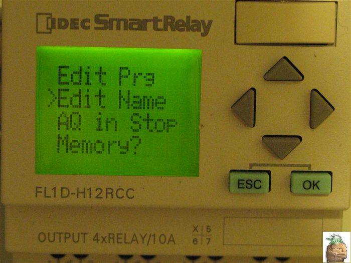
Press ESC key to return to the Program Editor Menu. As a Novelty (as it's not necessary for proper operation) we can name our Program/Flip Flop:

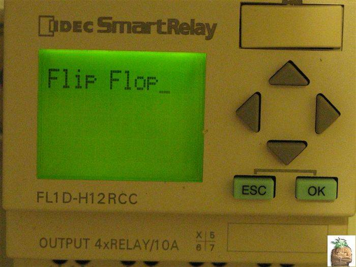
AND THERE YOU HAVE IT, a Functioning Digital Ballast Flip-Flop. We just have to make the Ballast and Lamp Connections, which I'll take care of in the next post.
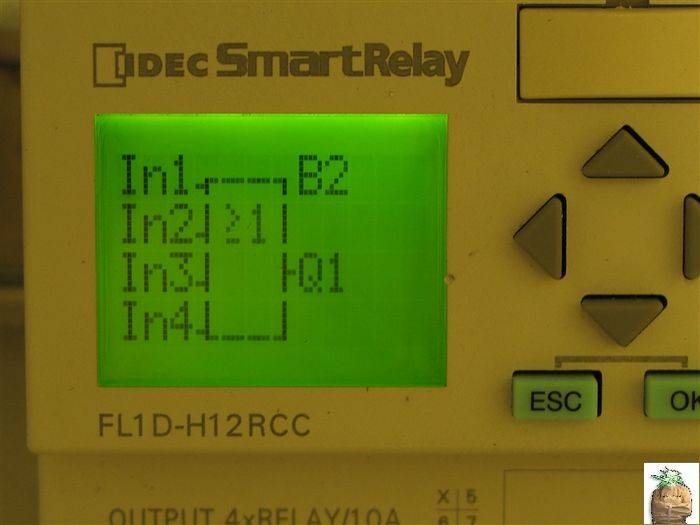
Just for reference, Here is a COMPLETE overview of the flip flop program so you can visualize how it should be structured:
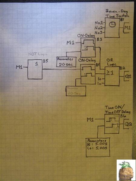
EDIT: With some trial and error, I have come to the conclusion the 20 second timers should be EXTENDED out to 2 minutes or longer (I am currently using 5 minutes for my dwell time) to allow the ballast to cool a bit and allow the ballast capacitor time to discharge. When I used 20 sec, the magnetic ballast didn't always fire AND upon consultation with other digital ballast users who have said you DO NOT want to drop/reapply ballast power rapidly as it can cause a digital ballast to FAIL and we wouldn't want that.
D.I.Y. Ballast Flip-Flop Programming Part 2
Now, we have provided a statement that will Power the Ballast for the HALF of a 24 hour period when M1 is activated by the 7-Day Timer. We need to now go back to the OR Gate of this line of the program and write the second half of the Ballast Power Code.
Press the Right Arrow THREE times to return to this screen:
Highlight In2 with your cursor and scroll to the Special Function menu:
Press OK and the first selection is the ON-Delay Timer again:
Now we have to make the On-Delay to work opposite of the first half of this "rung" of the program. Select the General Function Menu:
In the General Function Menu, select the NOT Gate using the OK button:
Now we Re-Use the M1 Virtual Output under the Co Menu ( which I forgot to get the picture of ):
And, Remember to go back and set the amount of time delay under the Par menu of the On-Delay Timer:
Return to the Q1 bracket at the beginning of this rung because it is now complete. Now, we can program for the LSRs to function properly. Change the Q1 to Q2:
And select the Special Function menu again:
Press OK and scroll through this menu to the ON-OFF Delay Timer:
(This function will ensure that the contacts are ALWAYS closed before the ballast fires)
Select Co in the Timer's Menu:
And make M1 the trigger for the On-Off Delay Timer:
Enter the On-Off Delay Timer Parameter Menu:
And set a suitable ON and OFF times that will cause contact closure during the BPR(s) OFF cycle:
Press ESC key to return to the Program Editor Menu. As a Novelty (as it's not necessary for proper operation) we can name our Program/Flip Flop:
AND THERE YOU HAVE IT, a Functioning Digital Ballast Flip-Flop. We just have to make the Ballast and Lamp Connections, which I'll take care of in the next post.
Just for reference, Here is a COMPLETE overview of the flip flop program so you can visualize how it should be structured:
EDIT: With some trial and error, I have come to the conclusion the 20 second timers should be EXTENDED out to 2 minutes or longer (I am currently using 5 minutes for my dwell time) to allow the ballast to cool a bit and allow the ballast capacitor time to discharge. When I used 20 sec, the magnetic ballast didn't always fire AND upon consultation with other digital ballast users who have said you DO NOT want to drop/reapply ballast power rapidly as it can cause a digital ballast to FAIL and we wouldn't want that.
Last edited:
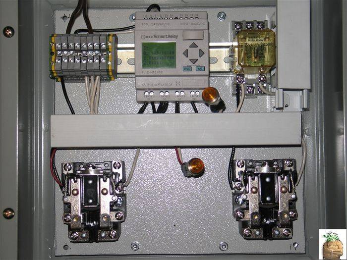
D.I.Y. Ballast Flip-Flop Operation And Relay Wiring
D.I.Y. Ballast Flip-Flop Operation And Relay Wiring
OK, we've done all the work, so let's see how this works. I have indicator lamps connected to the relay coils so you guys can "see" the relay close.
ESC key out to this screen:
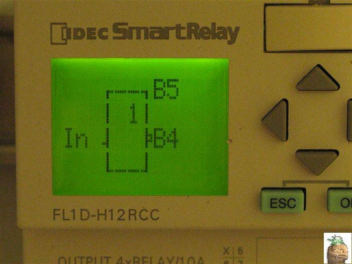
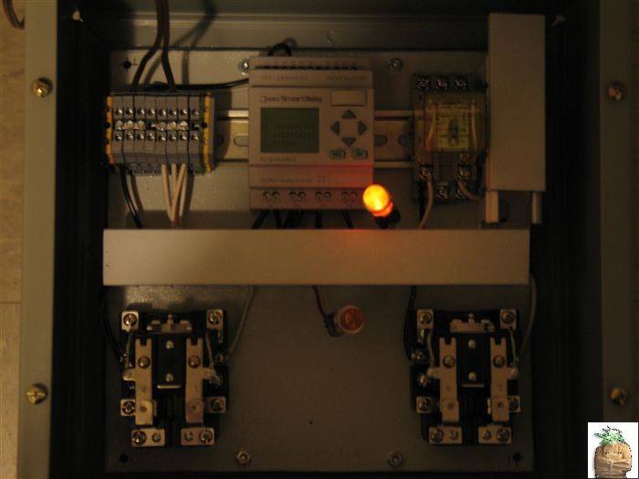
Now we have to take into consideration what state M1 Virtual Output is in. For Discussion's sake we'll say M1=0/OFF/lo. On MY Flip Flop that means we are between 6 P.M. - 6 A.M. So say we hit the OK key at EXACTLY 6 A.M:
So with M1 in the OFF state, scroll down to Start and press OK. The Relays are BOTH OPEN like this:
Now, because M1=0/OFF/lo the LSRs remain open and after 20 seconds the BPR(s) close:
The Flip Flop will remain in this state for 12 hours. At 6 A.M. M1 is triggered ON by the 7-Day time clock:
After 5 Seconds:
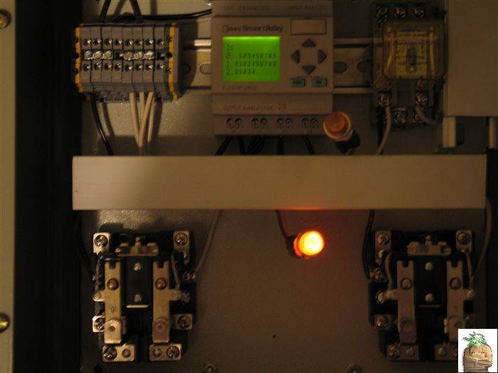
After 20 Seconds and for the next 12 hours:
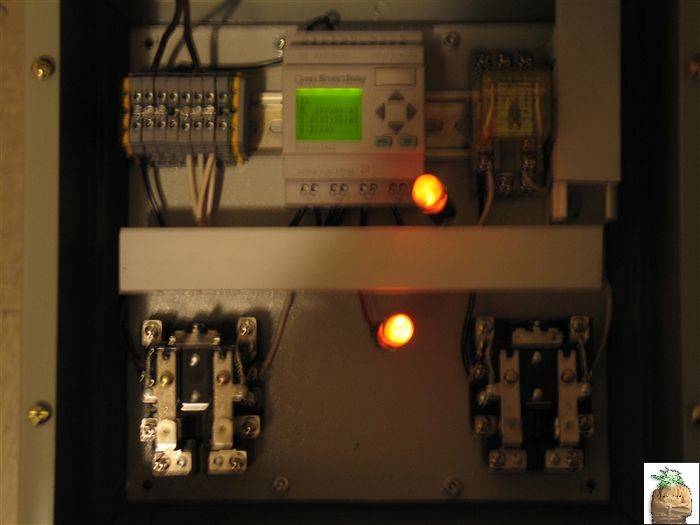
When 12 hours pass ( 6 P.M. ) the 7-Day Time Clock OPENs M1:
And the cycle restarts from the top
Reserved for future use
P.S. : Hydrostatic, can you please delete your post and put it back AFTER this one?
I did not realize I would need this many posts for my step by step pictures and I think it would be easier to under stand my posting if they were all grouped together. Thanks in advance, and I'll be glad to walk ya through the necessary equipment and programming after the D.I.Y. Flip Flop is done.
Note to self: PH & EC/TDS Monitoring/Auto-Adjustment for Hydrostatic...Thanks dood!!!
D.I.Y. Ballast Flip-Flop Operation And Relay Wiring
OK, we've done all the work, so let's see how this works. I have indicator lamps connected to the relay coils so you guys can "see" the relay close.
ESC key out to this screen:
Now we have to take into consideration what state M1 Virtual Output is in. For Discussion's sake we'll say M1=0/OFF/lo. On MY Flip Flop that means we are between 6 P.M. - 6 A.M. So say we hit the OK key at EXACTLY 6 A.M:
So with M1 in the OFF state, scroll down to Start and press OK. The Relays are BOTH OPEN like this:
Now, because M1=0/OFF/lo the LSRs remain open and after 20 seconds the BPR(s) close:
The Flip Flop will remain in this state for 12 hours. At 6 A.M. M1 is triggered ON by the 7-Day time clock:
After 5 Seconds:
After 20 Seconds and for the next 12 hours:
When 12 hours pass ( 6 P.M. ) the 7-Day Time Clock OPENs M1:
And the cycle restarts from the top
Reserved for future use
P.S. : Hydrostatic, can you please delete your post and put it back AFTER this one?
I did not realize I would need this many posts for my step by step pictures and I think it would be easier to under stand my posting if they were all grouped together. Thanks in advance, and I'll be glad to walk ya through the necessary equipment and programming after the D.I.Y. Flip Flop is done.
Note to self: PH & EC/TDS Monitoring/Auto-Adjustment for Hydrostatic...Thanks dood!!!
Last edited:
Shlomo: Your I/O structure for your project is QUITE simple:
(Time Clock OR HIGH Temperature Switch Input) = Fan Relay Output
The Programming would be a bit more complex and I'd have to work on it a bit...
(Time Clock OR HIGH Temperature Switch Input) = Fan Relay Output
The Programming would be a bit more complex and I'd have to work on it a bit...
BUMP
FLIP-FLOP's DONE
FLIP-FLOP's DONE
Hurting? Mines brokenasher1er said:My brains hurting

I suspect if I could follow it, I'd be even more impressed than I am.
FreezerBoy: These are actually quite simple to operate.
If you make the screen display Exactly In The Order I have, before you press enter, Then you will have the same functioning program as I have. The Photos are of the actual functions you will need to put in place for this to work.
If you make the screen display Exactly In The Order I have, before you press enter, Then you will have the same functioning program as I have. The Photos are of the actual functions you will need to put in place for this to work.
vodoochild
Active member
Very impressive! You made a master control panel for pennies on the dollar buying it retail. Nice job man!
Hydrostatic
Member
imnotcrazy,
Thanks for taking the time to share some knowledge, I'll be looking forward to pH/EC/TDS controller.
Note to self: PH & EC/TDS Monitoring/Auto-Adjustment for Hydrostatic...Thanks dood!!!
Thanks for taking the time to share some knowledge, I'll be looking forward to pH/EC/TDS controller.
Shlomo
Member
imnotcrazy said:Shlomo: Your I/O structure for your project is QUITE simple:
(Time Clock OR HIGH Temperature Switch Input) = Fan Relay Output
The Programming would be a bit more complex and I'd have to work on it a bit...
Well I know how to program in my timer function now - thanks!
Next I've got to determine how to split the program into subroutines... and after that, how would I structure the thermostat subroutine? I should probably be thinking about this visually...
Oh, and I guess I should actually read the manual and figure out what all those function blocks do

Sooo lazy
Shlomo: Basically, If you are going to ADD the ventilation programming to my program:
All you need to do is start with the next available OUTPUT Q3
The next step would be an OR Gate that way you can make the statement: Q3 = High Temperature Switch OR Fan Cycling Timer.
Leg one of the Or gate is connected to I1 AKA HIGH temperature input
And the other leg to a Cyclestat A.K.A. Recycle Timer Which I have to look into programming
AND YES, the easiest way to debug etc is to be looking at the program AS A WHOLE
Last edited:
Xtrakritical
Active member
Awesome Thread!
Awesome Thread!
Hey INC,
Nice write up Bro!
We appreciate you taking the time to document the step by step with pics!
That should really help others out when they are sooo close but cant figure out what went wrong.
You amaze me with your skillz sometimes, you border genius / insanity mang!
DIY of the year material here...
Great Job!
Xtra
U
ureapwhatusow
not crazy just next level
excellent thread
excellent thread

INC - We're going into business for real man. We could wire and build ANYTHING.
Lots of $ in HVAC/R bro. We'll talk...
Lots of $ in HVAC/R bro. We'll talk...
K
kelimmo
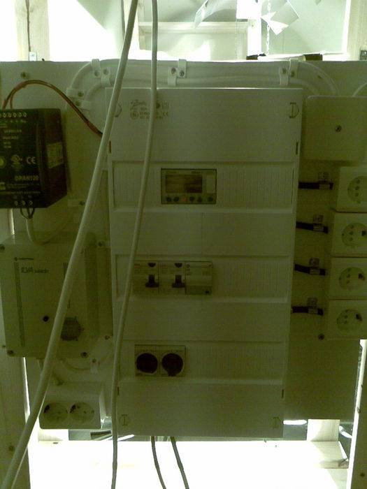
That's where the evolution of my co2-/pump interval/lamp + delay controller has come so far.
It's behind 3x 16A fuses at 230V euro current and operates 2x 25A contactors (1 missing in the pic) and for pumps and co2 solenoid valves (overkill? yes
") ) 4x 20A mini contactors for the lamps operated on two channels and two of the 16 amp phases.
) 4x 20A mini contactors for the lamps operated on two channels and two of the 16 amp phases.The relay controller is a Crouzet Millennium 3 24V as in a computer programmable version with analog inputs for co2, humidity, temp sensors and such.
Everything is behind 30mV RCCBs and quick fuses.
Last edited:
kelimmo: I like how your controller has ALL of the needed, switched functions integrated into ONE controller. Did you build or purchase that? It's built pretty nicely.
That's what I am planning to do as well, these controllers are also computer programmable. I am going to order the cable and software when I get the Analog I/O Module and CO2 probes
That's what I am planning to do as well, these controllers are also computer programmable. I am going to order the cable and software when I get the Analog I/O Module and CO2 probes
