
Cerathule
Active member
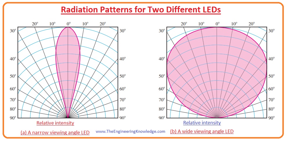
In theory an approximation of the diminishing over distance could be formulated if the beam angle of the diode is known. The light disperses in the shape of a cone. Both volume of sphere and cone can be calculated, and a co-factor derived by dividing the sphere's volume by the cone's.
For 90° beam angle COBs that should be about 6.
But ofc, the hardware doesn't emit the light so homogenously, and the cone isn't round-shaped at its bottom, which would be the correct geometric form to use.
Still usefull to give an idea how different LEDs deliver light than HIDs in an open reflector.


") Assuming a finite amount of peanut butter
Assuming a finite amount of peanut butter 


