A while ago I started making my own grow room controller. Mainly with cheap Arduino components purchased on Ebay. My knowledge was very limited, but I managed to put together a (somewhat) working controller. This controller is far from finished, I see it as version V. 1.0. Plenty of room for improvements and upgrades. That is the reason I wanted to publish this to Icmag. For the purpose of helping/receiving help/inspiring others to make the same project and to document my progress. I wanted to give back to the people of the internet, since I have used a ton of tutorials to make this work.
My requirements for the controller started like this:

Intro:
This is the main layout of the controller. It can be mounted on the wall or placed on a table. The project box is quite big, but there is a lot of empty space inside so a smaller box can be used.
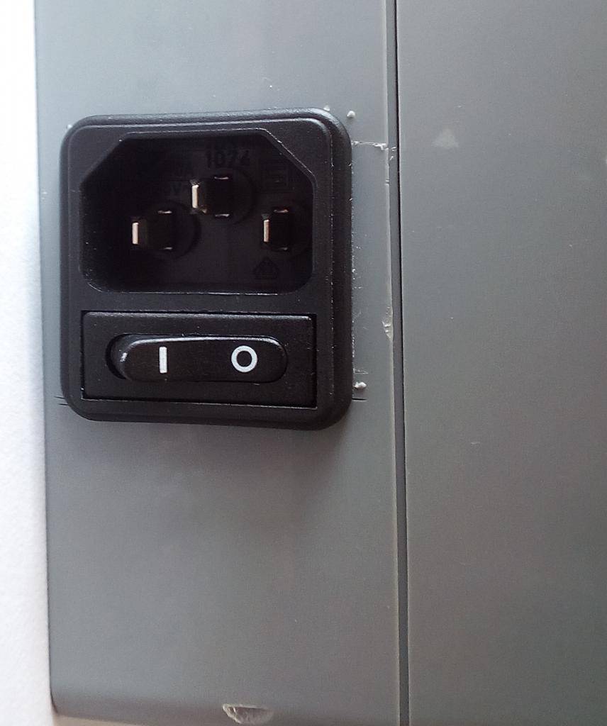
Information is displayed onto an LCD screen (20x4). The controller is powered by 1x 220V AC plug on the left side, with ON/OFF option. Underneath the controller, there is a RESET button.
A USB cable is also sticking out of the box, but this is just for testing/upgrading phase, so it is easier for me to upload new code onto the Arduino.

AC power-outputs:
The controller has 6x AC outlets. #1 for light. #2 for fan-out. #3 for fan-in. #4 for circulation fan. #5 for humidifier. #6 is not used (yet).
These outlets are controlled by the 8-channel relay board, which is controlled by the Arduino. All power used by the grow-room is supplied by the controller (for a maximum of 10A). The power entering the controller is connected to a muffer, which spreads the power in a parallel-series to all the outlets. I am not schooled in AC power, but in DC power so I am not sure this is the best/safest way to do it. Let me know if there are better ways.
Vegetation and flowering phase:
In a future version of the controller, a rotary encoder switch will be used to choose light intervals, as well as desired temp/hum values for triggering fans and dehumidifier. But for now, there are two separate codes. One for veg phase and one for flower phase. Intervals and temp/hum values are written in the code, on the IDE.
Time tracking:
The controller is not connected to the internet, nor does it have a real-time clock. So basically it only knows when it was turned on, and starts counting milliseconds at that moment. This means if Flowering phase is used, and the controller is turned on at 12pm, it will do so forever. There is on the third line of the LCD display a “Days NR#” since it was turned on. So if veg time should be 4 weeks, user will know 4 weeks have passed when days counter hits Day Nr #28.
Note: The 1 0 0 (or 0 0 0/ 1 1 1) at the bottom of the LCD screen indicates whether or not circulation fan is on/off, if in/out-take fans are on/off and if dehumidifier is on/off.
Controlling intake/outtake fans & dehumidifier:
[FONT="]The intake/outtake fans are controlled by the DHT22 sensor. The Arduino compares these readings to the desired/set values in the code, and triggers the relay ON or OFF if values are met.
As for the dehumidifier, the humidity readings from the DHT22 sensor is sent to the Arduino, which compares them to the set value of when the dehumidifier should be turned on.
A thermostat principle is used to achieve this. FX when temp hits 29 degrees Celsius, in/out-take fans are turned ON. They stay ON, until temp hits 22 degrees Celsius.
[/FONT]
Components list:
Hardware setup:
First we have the Arduino Uno powered by its own power supply.
The DHT22 sensor is connected to pin(5), 5V and ground on the Arduino.
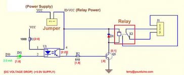
The 8-channel relay is also powered by its own power supply. This power supply is connected to pin(JD-VCC) and ground on the far right side of the relay. The relay is also connected to 5V from Arduino. The relay data-pins are connected to Arduino pin(7,8,9,10,11,12).
The LCD(20x4) screen is connected to Arduino SCL and SDA pins, 5V and ground.
Reset-button is connected to 5V and ground. The button is a momentary switch, so when triggered 5V and ground are connected, in which the Arduino is reset (Same as turning it off and on again).

Software setup:
I am using the official Arduino.cc IDE for writing code. I will not explain the basic fundamentals of Arduino coding, since there are many great tutorials on this subject. So if this is totally alien to you, I would recommend looking into some beginners guides on Arduino programming. I will try to shortly explain the changeable parts of the code, without making this tutorial any longer than needed. Questions are very welcome on workings of the code, or on things that I did not explain properly. I will try to explain as best as I can. (Note: This code will not work if all pins are not connected exactly like in my setup!)
The only difference in Vegetation phase and Flower phase code, is light schedule, the chosen temp/humidity values for when the in/out-take fans should be triggered, and also when the dehumidifier is turned on/off. All these values can be modified in the code.
[FONT="]The code is organized in different parts. Fx. “Light timer”, “Temperature control”, ” Humidity control” and so on, for easily overview and modifying of the code.[/FONT]
Code that should be modified for desired thermostat values is this part (Line 30+31 in code):
Humset=55 is when the dehumidifier should be turned ON. 55 meaning 55%. And like before, humreset=40, means it will turn OFF when humidity hits 40%.
Next part of the code which can be modified is light timer (Line 110-123):
The last part of the code which can be modified to your desired value is circulation timer. This controls the fan inside grow room. It is initially set at 5mins ON and 5mins OFF interval (Line 127-135):
This was the 3 parts of the code which can be modified to fit the desired thermostat temp/hum value, and timer intervals. Everything else can be modified in the code, but these 3 parts are the key components, as changing a lot of the other code stuff will give errors in running the controller. For questions on code, feel free to ask away and I will try to answer as best as I can. I myself, is quite new to Arduino, so I might not be able to answer everything.
[FONT="]One last thing I would like to note. The LCD screens light turns OFF when light timer goes to OFF mode, so LCD light does not spread confusing unnecessary light into the room in dark period.[/FONT]
Download links to Vegetation and Flowering phase code:
http://www.mediafire.com/download/r3sdx3l4u84uxx3/Veg_and_Flower_phase_sketch.zip
Libraries used in Arduino IDE for creating Flowering and vegetation Phase code:
http://www.mediafire.com/download/40qstnapg48qubb/Grow_controller_arduino_libraries.zip
Contains following libraries:
For those who are familiar with Arduino or other microcontrollers, I think this guide will be somewhat understandable, although I think some of the points in this tutorial could have been written differently or in a more teachable-friendly way. I hope this whole thing is understandable and not just a long confusing mess. Let me know! And if there are any questions what so ever, I will try to answer it as best as I can. I hope this helps someone in need, or sparks new curiosity amongst the human internet-population. Thanks for a great forum! Goodbye for now, until next time.
My requirements for the controller started like this:
- Auto-control light. 18/6 and 12/12 schedule
- Thermostat controlled in/out-take fans
- Auto-controlled dehumidifier
- Auto-controlled room circulation fan
Intro:
This is the main layout of the controller. It can be mounted on the wall or placed on a table. The project box is quite big, but there is a lot of empty space inside so a smaller box can be used.
Information is displayed onto an LCD screen (20x4). The controller is powered by 1x 220V AC plug on the left side, with ON/OFF option. Underneath the controller, there is a RESET button.
A USB cable is also sticking out of the box, but this is just for testing/upgrading phase, so it is easier for me to upload new code onto the Arduino.
AC power-outputs:
The controller has 6x AC outlets. #1 for light. #2 for fan-out. #3 for fan-in. #4 for circulation fan. #5 for humidifier. #6 is not used (yet).
These outlets are controlled by the 8-channel relay board, which is controlled by the Arduino. All power used by the grow-room is supplied by the controller (for a maximum of 10A). The power entering the controller is connected to a muffer, which spreads the power in a parallel-series to all the outlets. I am not schooled in AC power, but in DC power so I am not sure this is the best/safest way to do it. Let me know if there are better ways.
Vegetation and flowering phase:
In a future version of the controller, a rotary encoder switch will be used to choose light intervals, as well as desired temp/hum values for triggering fans and dehumidifier. But for now, there are two separate codes. One for veg phase and one for flower phase. Intervals and temp/hum values are written in the code, on the IDE.
Time tracking:
The controller is not connected to the internet, nor does it have a real-time clock. So basically it only knows when it was turned on, and starts counting milliseconds at that moment. This means if Flowering phase is used, and the controller is turned on at 12pm, it will do so forever. There is on the third line of the LCD display a “Days NR#” since it was turned on. So if veg time should be 4 weeks, user will know 4 weeks have passed when days counter hits Day Nr #28.
Note: The 1 0 0 (or 0 0 0/ 1 1 1) at the bottom of the LCD screen indicates whether or not circulation fan is on/off, if in/out-take fans are on/off and if dehumidifier is on/off.
Controlling intake/outtake fans & dehumidifier:
[FONT="]The intake/outtake fans are controlled by the DHT22 sensor. The Arduino compares these readings to the desired/set values in the code, and triggers the relay ON or OFF if values are met.
As for the dehumidifier, the humidity readings from the DHT22 sensor is sent to the Arduino, which compares them to the set value of when the dehumidifier should be turned on.
A thermostat principle is used to achieve this. FX when temp hits 29 degrees Celsius, in/out-take fans are turned ON. They stay ON, until temp hits 22 degrees Celsius.
[/FONT]
Components list:
- Arduino Uno
- 8 channel 5V optocoupler Relay (Too big since i only use 5 channels)
- DHT22 Sensor
- 20x4 I2C LCD display
- Power supply for Arduino (9V, 1A)
- Power supply for Relay (5V, 2A)
- Assorted wires + other small installation stuff
- Project box
Hardware setup:
First we have the Arduino Uno powered by its own power supply.
The DHT22 sensor is connected to pin(5), 5V and ground on the Arduino.
The 8-channel relay is also powered by its own power supply. This power supply is connected to pin(JD-VCC) and ground on the far right side of the relay. The relay is also connected to 5V from Arduino. The relay data-pins are connected to Arduino pin(7,8,9,10,11,12).
The LCD(20x4) screen is connected to Arduino SCL and SDA pins, 5V and ground.
Reset-button is connected to 5V and ground. The button is a momentary switch, so when triggered 5V and ground are connected, in which the Arduino is reset (Same as turning it off and on again).
Software setup:
I am using the official Arduino.cc IDE for writing code. I will not explain the basic fundamentals of Arduino coding, since there are many great tutorials on this subject. So if this is totally alien to you, I would recommend looking into some beginners guides on Arduino programming. I will try to shortly explain the changeable parts of the code, without making this tutorial any longer than needed. Questions are very welcome on workings of the code, or on things that I did not explain properly. I will try to explain as best as I can. (Note: This code will not work if all pins are not connected exactly like in my setup!)
The only difference in Vegetation phase and Flower phase code, is light schedule, the chosen temp/humidity values for when the in/out-take fans should be triggered, and also when the dehumidifier is turned on/off. All these values can be modified in the code.
[FONT="]The code is organized in different parts. Fx. “Light timer”, “Temperature control”, ” Humidity control” and so on, for easily overview and modifying of the code.[/FONT]
Code that should be modified for desired thermostat values is this part (Line 30+31 in code):
In this part, tempest=26 is when the out/in-take fan should be turned ON. 26 meaning 26 degrees Celsius. Tempreset=19, is when the out/in-take fans should be turned OFF again. So when temp hits 26C fans turn ON, and then temp hits 19C, they turn OFF.int tempset=26, tempreset=19; // For vegfase: 20-30C // For flowerfase: 18-26C
int humset=55, humreset=40; // For vegfase: 40-70% // For flowerfase: 40-50%
Humset=55 is when the dehumidifier should be turned ON. 55 meaning 55%. And like before, humreset=40, means it will turn OFF when humidity hits 40%.
Next part of the code which can be modified is light timer (Line 110-123):
In this light timer part, interval can be modified to the desired amount of hours ON/OFF. In this part, it is set to 43200000 ms. Which equals 12 hours. So when Arduino turns on to start with light is OFF, it then turns ON. When light has been ON for 12 hours, it goes to next interval which is also 12 hours. So continually 12 hours OFF and 12 hours ON. So this part is different from Vegetation phase, in which first interval is set at=64800000ms which is 18 hours ON, and second interval is at=21600000ms which is 6 hours OFF.if (currentMillis - previousMillis >= interval) {
previousMillis = currentMillis;
if (lightState) {
lightState = LOW;
interval = 43200000; // 64800000 = 18 hours ON // 1 hour = 3600000
myDisplay.backlight();
} else {
lightState = HIGH;
interval = 43200000; // 21600000 = 6 hours OFF
myDisplay.noBacklight(); }
[FONT="]digitalWrite(lightPin, lightState); } [/FONT]
The last part of the code which can be modified to your desired value is circulation timer. This controls the fan inside grow room. It is initially set at 5mins ON and 5mins OFF interval (Line 127-135):
So here we can see first interval2 is set to 300000ms, which equals to 5 mins. This can be modified to whatever interval2 is desired. 1 min = 6000ms.if (currentMillis - previousMillis2 >= interval2) {
previousMillis2 = currentMillis;
if (fanroomState) {
fanroomState = LOW;
interval2 = 300000; // 300000 = 5 mins ON // 1 min = 60000
} else {
fanroomState = HIGH;
[FONT="] interval2 = 300000; } // 300000 = 5 mins OFF [/FONT]
This was the 3 parts of the code which can be modified to fit the desired thermostat temp/hum value, and timer intervals. Everything else can be modified in the code, but these 3 parts are the key components, as changing a lot of the other code stuff will give errors in running the controller. For questions on code, feel free to ask away and I will try to answer as best as I can. I myself, is quite new to Arduino, so I might not be able to answer everything.
[FONT="]One last thing I would like to note. The LCD screens light turns OFF when light timer goes to OFF mode, so LCD light does not spread confusing unnecessary light into the room in dark period.[/FONT]
Download links to Vegetation and Flowering phase code:
http://www.mediafire.com/download/r3sdx3l4u84uxx3/Veg_and_Flower_phase_sketch.zip
Libraries used in Arduino IDE for creating Flowering and vegetation Phase code:
http://www.mediafire.com/download/40qstnapg48qubb/Grow_controller_arduino_libraries.zip
Contains following libraries:
- DHT library
- Liquid crystal I2C library
- Time-master library
For those who are familiar with Arduino or other microcontrollers, I think this guide will be somewhat understandable, although I think some of the points in this tutorial could have been written differently or in a more teachable-friendly way. I hope this whole thing is understandable and not just a long confusing mess. Let me know! And if there are any questions what so ever, I will try to answer it as best as I can. I hope this helps someone in need, or sparks new curiosity amongst the human internet-population. Thanks for a great forum! Goodbye for now, until next time.