What's new
  • Happy Birthday ICMag! Been 20 years since Gypsy Nirvana created the forum! We are celebrating with a 4/20 Giveaway and by launching a new Patreon tier called "420club". You can read more here.
  • Important notice: ICMag's T.O.U. has been updated. Please review it here. For your convenience, it is also available in the main forum menu, under 'Quick Links"!

DYI multi-CFL-hood with remote ballast box

NKOTS

follow the pink rabbit!
Veteran
hi everyone,

i was requested by other fellow growers to share construction details of a multi-CFL-hood with remote ballast which i built for the rabbit burrow.

let me answer these requests and share something with the ICM community.

DYI guide to your own multi-CFL-hood.

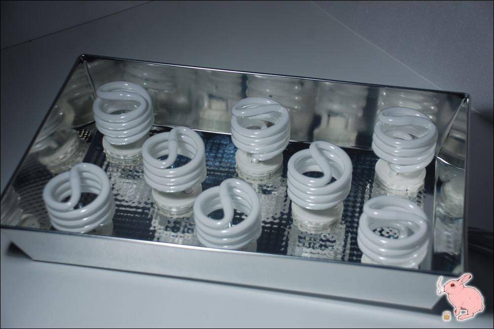
the end product (hood) looks like this:


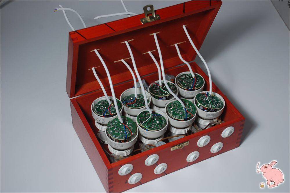
while the remote ballast looks like this:


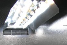
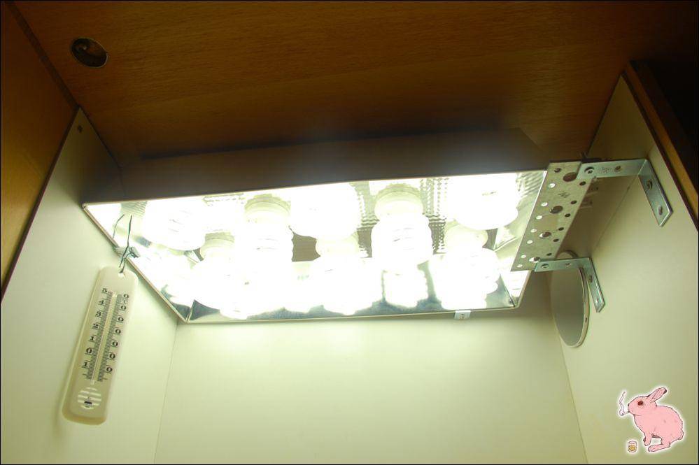
and here's the gear in action:


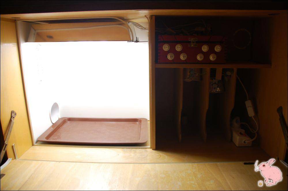
i will cover both contraptions (hood & ballast) one by one for everyone to follow easily.


to start with, let me say big thanks to grouchy, who opened my eyes for this concept and inspired me in his remote ballast thread.
i thought this idea has many advantages and i decided to install it in my rabbit burrow, with some amount of upgrade added to grouchy's original build.

benefits of remote ballasting:

- CFL is cut in half, therefore it only takes 50% of original height (the rest sits in external ballast box), besides you don't need the fixtures in your grow area - this way you can save a lot of space in your cab (especially beneficial for microgrowers)
- CFL ballasts do warm up a bit and due to their external location their heat does not impact cab interior
- if you wish you can add switches which allow lighting control easily. each CFL can be switched on/off in any moment with no fuss
- deinstallation is a piece of cake in case you need to do some maintenance because each element is granted easy access
 

NKOTS

follow the pink rabbit!
Veteran
OK let's get to work. here's what you need for the build:

EQUIPMENT - HOOD

a) baking pan whose dimensions suit your cab (in my case it is 15 x 10 inch / or 39 x 23cm)
b) CFLs - the more you can fit in the pan the better but watch out the temps (in my case 8x23W = 184W)
c) some 4-gauge cable whose every gauge has different colour (i could only find a 6-gauge cable that guarenteed 4 different colours)
d) screws, bolts, plastic holders etc.


HANDY TOOLS

a) screwdriver
b) driller + metal drilling bits + hole drillers for wood
c) pliers + sharp knife
d) markers in 4 different colours
e) very useful yet not neccessary: soldering gun
 

NKOTS

follow the pink rabbit!
Veteran
DIY STEP BY STEP

PART 1: THE HOOD


step 1. place your CFLs on the hood (baking pan?) and mark their future positions
step 2. drill small holes in the hood, this will let your wiring through. you need 1 hole for the bit and 1 for the wires


time to deinstall your CFLs

step 3. gently separate two parts of the CFL with a small screwdriver. inside there is some electrical stuff. you need to find 4 pins that lead small wires to the bulb (tube). these pins are marked (in my case: d1, d2, d3, d4 - see on the pic below).


step 4. mark every wire with a different colour and WRITE DOWN which wire goes to which pin. (the easiest way to get it right is to use the same colours as in your 4-gauge cable)
step 5. detach the wires from the pins (use small pliers) - this way your CFL gets separated into 2 parts.


NKOTS

follow the pink rabbit!
Veteran
step 6. you will deal with the electrical part later on, now you need to install the tube to the hood. first drill the tube casing right in the middle to make a hole for the screw.
step 7. connect (preferably solder) corresponding wires with your 4-gauge cable - make sure you get the colours right or it won't work!


step 8. lead the cable through the hole in your hood.
step 9. on the other side of the hood add the screw and get it all together, sturdy and secure.


now you may want to make a test. you can connect corresponding colours of the cable back to the second CFL part (pins marked d1, d2...). if you did it correct, it should work when you connect to power source.

now proceed with all other CFLs the same way. at the end of this stage your hood could look like this:


in my case the tubes remain in the limits of the hood - they don't use any more space than that.

and this was the point!
 

NKOTS

follow the pink rabbit!
Veteran
now back to the electronic stuff.

DYI STEP BY STEP

PART 2: THE BALLAST BOX


EQUIPMENT

e) the box itself - well you need to look around what could be suitable for this purpose. it must be big enough to accommodate the electronicals but small enough for your available space.


f) CFL fixtures
g) a couple of loose wires
h) screws, bolts etc.
i) switches - this is an option that will allow you to turn each of your CFLs on/off at any given moment
j) pin connectors or another means of connecting small electronic cables

step 10. inside the box, place the fixtures on the 'floor' and mark their positions


step 11. now drill the holes in the lid above each fixture (you will lead the 4-gauge cables inside this way so make sure the diameter of the hole allows it)
step 12. drill a hole in the side of the box - you will lead main power cable this way (this is also a good moment to drill the inlets and outlets for ventilation of the ballast box – I actually did it at the very end of the project when i realized the temp was quite high. it would be far more convenient to have it done here)
step 13. optionally mark locations of your switches on the other side of the box and drill holes for them


NKOTS

follow the pink rabbit!
Veteran
step 14. insert 2 cables into every fixture and attach the fixtures to the 'floor' of the box


step 15. blue colour of the cables represents 'neutral' and it leads to one part of the power source. the browns lead to the opposite one
step 16. browns will go to the switches and then to power source
step 17. insert power cable into the box and attach to all your other cables inside


it looks a little tight and believe me it was a pita work with all this wiring. but the best is still to come!
 

NKOTS

follow the pink rabbit!
Veteran
at this stage it is wise to make a test - i performed it with regular incandescents. needless to say, they should all turn on.


step 18. now you will deal with the CFL body. attach (solder) the ends of your 4-gauge cables to appropriate pins (d1, d2...) - make sure you get the colours right.


note: i highly recommend to use soldering gun here. please notice the difference in the above pic.
on the left no soldering yet. on the right all securely soldered.


step 19. screw the CFL bodies into the fixtures in the box and lead the cables out through the holes in the lid.


step 20. you will later connect those cables with the ones coming from the hood. for this i used 4 electronic connectors but there are other (easier?) ways to connect them


step 21. you're almost done! just connect the hood to the ballast box and turn the power on. test your CFLs. test your switches.
 

NKOTS

follow the pink rabbit!
Veteran
step 22. make sure the temps in the box are moderate. if it heats up too much, i advise to vent the ballast box just like you vent your grow area (small PC fan and passive inlets should do fine)


will this work at all?


hooray!


END REMARKS

1. the cables that connect the ballast box to the hood should have quite thick gauges, this way the whole system heats up less. unfortunately the thicker they are, the harder to process them as there is a considerable number of CFLs to connect.
2. the inside of the ballast box may heat significantly. in such case i recommend to vent it with a little fan.
3. to avoid fire hazard you may also install a temp fuse that will cut power off once the temperature reaches certain level (there several levelsto choose, check out at your electrical supply)
4. it is recommended to keep the cables between the ballast box and the hood as short as possible. otherwise the ballasts heat up more. i tested at 2ft (60cm) and it worked fine.
5. there are many ways to install your hood in the growbox. i decided to place it on curved metal elements. it allows me to take the hood out with ease for maintenance.


that's all, folks! thanks for your attention.

and peace from the rabbit burrow! :smoke:
 
Wow, great ideas and very nice instructions! Thank you for sharing this, I'm very tempted to try it! It would be perfect for my mini veg chamber!
 

Keif

Member
People like you are why so many people have the courage to try new things. Great setup bro.
 

NKOTS

follow the pink rabbit!
Veteran
thx for comments, everyone, glad you like the build.
if this inspires anyone to do remote ballasting of CFL then all this posting proves valuable ;)


WILL IT GROW CANNABIS?

let me try to answer this Q.

run #1


run #2 growing currently:


stay relaxed, folks :smoke:
 

yesum

Well-known member
ICMag Donor
Veteran
Very impressive project you did there. I would not even attempt it.

I will give some friendly advice on the reflector though. The light from the ends of the bulbs and the light from the sides of the bulbs facing the sides of the pan will get out and down into your plants.

The side light from bulbs that is not next to the side of the pan will be trapped, going back and forth between the bulbs. The light goes out the sides in a radial or spokes of a wheel pattern. More light comes out of the sides than the ends because there is more surface area on the sides.

Putting the bulbs in a line with a v or u shaped reflector no more than 1 inch from the bulbs will give the plants a lot more light. The best would be y splitters and 2 bulbs per fixture, with several fixtures in a row with the v or u shaped reflector over them. This picture gives an idea but the reflector is several inches away from the bulbs which is a waste. https://www.icmag.com/ic/attachment.php?attachmentid=255678&stc=1&d=1392703490
 

Attachments

  • not this either.jpg
    not this either.jpg
    73.3 KB · Views: 31
Last edited:

Latest posts

Latest posts

Top