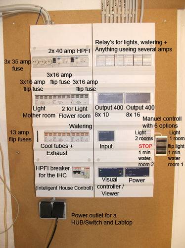
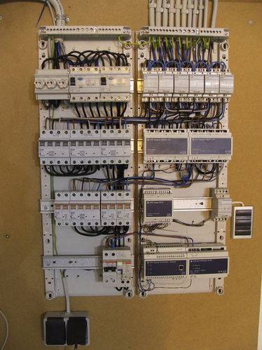
What's new
  • Happy Birthday ICMag! Been 20 years since Gypsy Nirvana created the forum! We are celebrating with a 4/20 Giveaway and by launching a new Patreon tier called "420club". You can read more here.
  • Important notice: ICMag's T.O.U. has been updated. Please review it here. For your convenience, it is also available in the main forum menu, under 'Quick Links"!

Application of Nano PLC In A Growroom

K

kelimmo

imnotcrazy said:
kelimmo: I like how your controller has ALL of the needed, switched functions integrated into ONE controller. Did you build or purchase that? It's built pretty nicely.

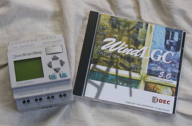
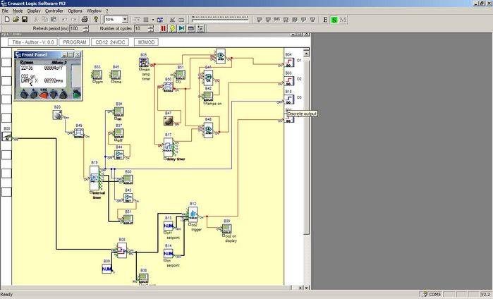
That's what I am planning to do as well, these controllers are also computer programmable. I am going to order the cable and software when I get the Analog I/O Module and CO2 probes


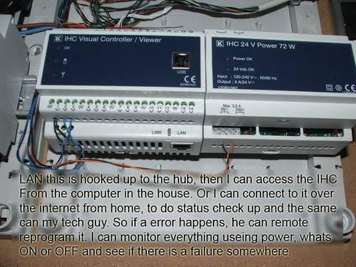
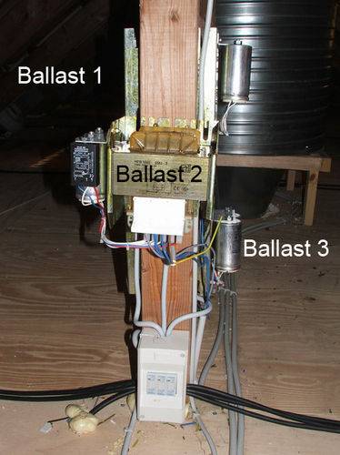
I've built everything on my own, DIY-style without any electrics education. It's actually pretty hard to get a hold of electrics equipment if you're not working at an company involved in electric installations around here.

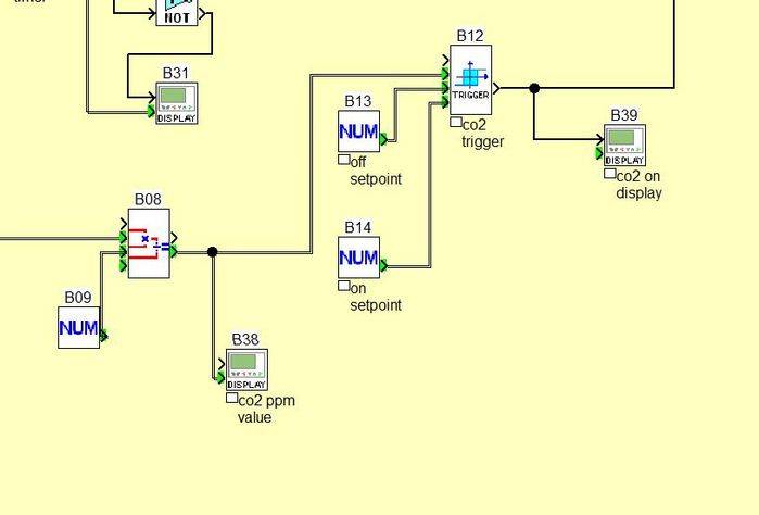
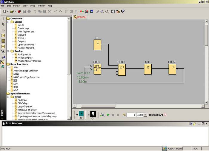
The logic is really amazing when it comes to ease of use and all different possibilities of use.
 

Budweiser13

Active member
INC thanks so much for this great tutorial. Now if you could just write a program for doing a Krypto multiflow controller for the buckets would be awsome.........I am going to be buying one of these PLC'S and trying to make the flip just how you have it......So could the multilow bucket controller be done with this PLC...here is a link.....http://www.icmag.com/ic/showthread.php?t=6341 I know others have done it but they never showed the programming scheme........
 
This is a GREAT thread few questions I noticed a few different models of these
FL1D-H12RCA
FL1D-H12RCC
FL1D-H12RCE
Can you explain the differences? Here is a link with them for sale with volume discounts http://www.newark.com/jsp/search/br...tk=gensearch_001&Ntt=categorynumber72535&Ntx= also I have some Telaire Co2 monitors theoretically I could hook that up to this right? Here is a tutorial thread on those Co2 controllers
http://www.icmag.com/ic/showthread.php?t=57090&page=1&pp=15
I would like to build a FULL greenhouse controller... light timer,ventilation control,co2 control,ac/humidity control, Basically a one stop plug in center lol. imnotcrazy if you could help I would be willing to send you one of these Telaires for free and I would make sure to post the step by step in this thread after I am done! just PM me thanks bud!
 
Last edited:
imnotcrazy,

Could you please PM me when you have a chance, I have a question for you before I go ahead and place my order for the required hardware. I am still not able to PM members due to my inadequate number of posts. Thanks.
 

Shlomo

Member
My PLC came in! Also, I got the software:


I also figured out my thermostat-air exchange program :D

What I wanted the PLC to do is turn my exhaust fan on for two minutes every 15 minutes, maintaining CO2 levels. Also, I wanted it to turn on whenever the temperature got too high, until the temperature evened out again! I figured it out, and the software helped a lot, by eliminating paperwork and allowing real-time simulation!

First, here is a shot of the software in action:


In the above picture, note the program diagram. The top block, labeled I, is the input block monitoring the physical input on the PLC, into which is wired a growroom thermostat switch. When the temperature goes too high in my growroom, the switch is turned ON, and so is the input block - otherwise, it is OFF. Now, the bottom four blocks, from left to right: the ON/OFF Delay Timer, an OR function block, the output to my relay controlling the fan (labeled Q1), and a NOT function block.

Got it? No? I'll explain.

The ON/OFF Delay Timer is set to turn on for 2 minutes and off for 15 minutes, and when it is connected to the output Q1, which is physically wired to the fan relay, the fan turns on and off at those intervals. BUT, the ON/OFF Delay Timer needs to know WHEN to start or stop the cycle - it can't just float in space! Fuck! So, I put in a NOT function block after output Q1 and loop it back to the ON/OFF Delay Timer. When Q1 (and subsequently, the fan) turns off after 2 minutes, the NOT block is like, "No you didn't, bitch," and tells the ON/OFF Delay Timer to switch to the 15 minute off cycle, after which, again, the NOT block tells it to initiate the two minute cycle, and so on, ad nauseum.

Now, what the fuck is that OR block between my ON/OFF Delay Timer and my Q1 output?

That OR block has that input block, I, tell it to turn on the Q1 output if the temperature in the room goes too high, activating the fan and cooling my room, regardless of the regular air exchanges! The ON/OFF Delay Timer goes into it too, so when the thermostat is not on, the regular air exchanges occur! If the temperature goes too high, the fan turns on until it is low enough, then the input block I deactivates, we wait fifteen minutes, and if the temperature hasn't gone too high by then, then an air exchange happens anyway!

A heater with a built in thermostat keeps the temps from going too low! Perfect temperatures forever! :muahaha:

Here is the simulation, though, in case it isn't clear. Blue means a low connection (OFF), red means hi (ON).

First, The ON/OFF Delay Timer is off, and so is Q1, but the clock is ticking!


Time's up, switch it up! You can see how the NOT block relays back to the ON/OFF Delay Timer. Note how the input block I stays cold, while the OR block passes on the signal of the ON/OFF Delay Timer!


HOLY SHIT IT'S TOO HOT IN THERE :yoinks:
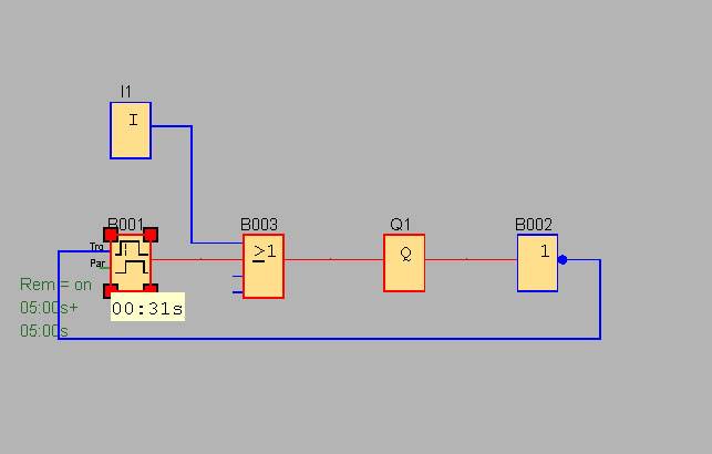
! I'VE GOT TEN MINUTES TO MY NEXT CYCLE! It's cool
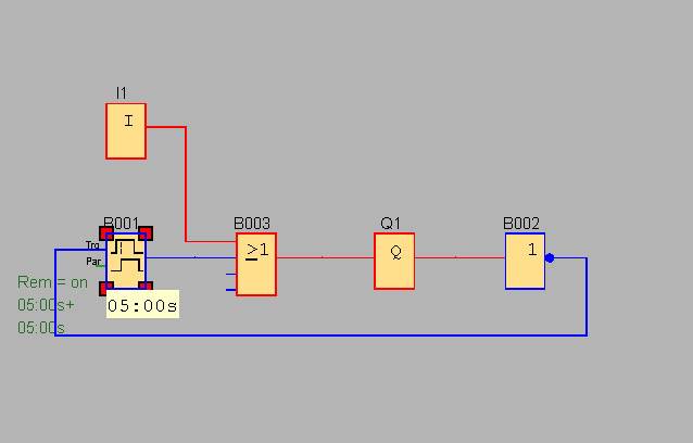
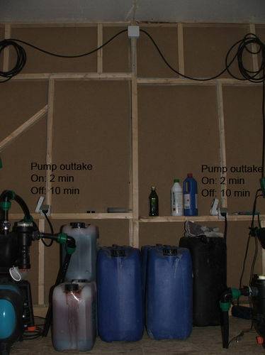
 :cool:, because the input block I is monitoring the physical input connected to a thermostat! The fan is turned on!


:pimp3:
 
K

kelimmo

And this is what it can look like when you play around with these programs:

 
Last edited:

Shlomo

Member
Heh heh yeah I'm programming the CO2 controller now, and with the flip-flop and thermostat things are getting a tad crowded...
 
This stuff is great thanks everyone!! I really want to dig into this soon but I need a few questions answered first.

Shlomo if you could help out my offer extends to you to as far as the CO2 sensor goes. I have a few Telaire Co2 Ventostat 8002's and would gladly ship you one if you could help me get this together. You can PM or just answer in this post either way i am going to post my step by step on here once its done.

Let me start out by explaining the rooms first(the build will also be documented in another thread). This is an old milking barn I plan on splitting into 3 rooms. I will enter through the middle room(supply room, etc) to my left will be a door to the bloom room which will have 5400 watts in two light banks one with 4x600w's over 3 4x4 ebb&flow tables and the other with 3x1000w's over water farm buckets all individually isolated these will have a walkway in the middle. The light banks will be connected on one end to roof vents with back draft dampers and a fan and the other end will lead into a fan which is connected to a 4 way duct the 3 open sides of which all have mechanical dampers hooked to them. The top dampers(which we will label DB1 for future reference) will lead into another roof vent.The bottom dampers(which we will label DB2 ) will lead to the bloom room. And the other dampers(which we will label DB3) will lead to the supply room/or veg room.

That leaves the veg room to my right once I enter my supply room obviously.That room will also be split in two with a walking row down the middle. It will 1x1000w on a mover going over buckets,mothers and a 4x4 tray the other side will be shelving down the whole room with T5's for clones. The 1000w will be hooked up similarly to the other room except only one fan that's connected to the roof input vent and no veg room discharge.

All this will allow me to grow not only different strains but have them all cycling at different times!

Now I will outline what Inputs and Outputs I believe I will have...

Inputs:

1. Thermostat #1 Located in the Bloom room
2. Thermostat #2 Located in the Veg room
3. Light Timer #1 Connected to 600w light row in Bloom room
4. Light Timer #2 Connected to 1000w light row in Bloom room
5. Co2 Sensor #1 Connected to Bloom room Co2 burner
6. Co2 Sensor #2 Connected to Veg room Co2 burner

Outputs:

1. Damper Bank #1 = Bloom Room roof vents(output)
2. Damper Bank #2 = Bloom Room room vents(distributes heat into BR)
3. Damper Bank #3 = Wall vents leading to veg/supply room
4. Veg Room Roof Vent(output)
5. Veg Room Wall Vent(distributes heat into bloom room)
6. Light Bank #1 plug set(for 4x600w's and 2 Vortex 8in fans)
7. Light Bank #2 plug set(for 3x1000w's and 2 Vortex 8in fans)
8. Plug in for Co2 Burner #1
9. Plug in for Co2 Burner #2

Here is what I will need to program into this thing..

1. Roof Vents(DB1) will need to be open only when lights are running except when DB2 or DB3 are triggered.
2. Bloom room vents(DB2) need to be triggered when thermostat 1 hits below 66 degrees and triggered closed at 75 degrees but ONLY when the lights are on.
3. Wall Vents(DB3) leading to veg room need to be triggered when thermostat #2 reads below 68 degrees except when DB2 is on cause DB2 always has top priority also if DB2 is off and therm 2 is reading 75 degrees or above I would like DB3 to shut off.
4. Veg Room Roof Vent always will be open as long as veg room wall vent is off
5. Veg Room Wall Vent(leading to BR) will be triggered on when therm 1 reads under 68 degrees but triggered off when it reads above 78 degrees
6. Plug Set #1 will be triggered by timer#1 and relays, each light timed to turn off/on 1 minute apart(so I don't have this huge electricity spike)
7. Plug set #2 will be triggered by timer #2 which will turn on 1 min after the last light on plug set #1 is triggered again these will turn each light on 1 min apart.
8. Single outlet #1 will trigger Co2 burner #1 and will be triggered when Co2 Sensor #1 hits below 1500ppm but will not trigger on when lights are turned off
9. Single outlet #2 will trigger Co2 burner #2 triggered by Co2 sensor #2

Ok here's what I really need to know and if you could guide me through this I would be willing to send you one of these Co2 sensors!

First Obviously I will need to know what PLC would best suite me. If you look back one page I gave a link to a few of these that are similar but I am unsure in how. I understand I will probably need an extension with more inputs/outputs to handle all the lights which one would be best for me?
What relays will be best for each function I described below and how many should I need?
Also what thermostats will work with these PLC's?

And the MOST important is can someone guide me through the programming step? I do believe once I figure out all this info I will be able to fully explain everything to my electrician buddy and we can wire it all up I will make sure to put that up!
Shlomo if you could guide me through this I bet the thread I write up will contribute for years to this community and I would GREATLY appreciate it ;) plus you would get a free Co2 Sensor!! lol
 
Last edited:

Shlomo

Member
I see what you're doing with the exhaust heat, Barn Growin', and all I can say is - awesome! Way to not waste energy! I guess one of the main challenges would be configuring your damper/thermostat program so that there is no conflicting logic, but it couldn't be too hard.

There is enough room on the base IDEC nano-plc for all your inputs, but not for all your outputs. You'll need to buy three expansion slots, each containing 2 outputs, for about $60 a piece, which, with the original piece at about $150, the cable and software at $150, will run about $480-$500 American for an IDEC nano-PLC "solution." I don't know other PLC's, but I've read OMRON is the bee's mothafuckin' knees.

It is a shame you're not using a lighting flip-flop for the two flowering spaces, as this would save additional programming, wiring, and output slots, and, most importantly, hardware costs. I'm using my flip-flop relay bank to control thermostat and CO2 sensor data inputs, as well as all lights on and other outputs. This way I use one exhaust fan for two rooms (dampers controlled by the flip-flop), one ballast for each two lights, one co2 burner for each two rooms (splitter valve off the flip-flop) - which is cheaper, all thanks to the 12/12 light cycle Jah bless it :D But, I understand your space may not allow for that...

To be clear, I'm still learning the IDEC system (though it is DEAD EASY - just memorizing what function blocks do). I still don't know which thermostat input I'll be using, what kind of CO2 sensor I'll use, if there is an option/preference between analog and digital, cost, etc... so I can't tell you how to program your setup now. It would be good, if you were using the nanos, to order the goods and work out a program, then post it up and I'll check it out, run simulations on this end and debug for practice?

Anyways, when I get the CO2 program figured out, I'll post it up, though I have a feeling imnotcrazy will come through soon and show us his finished CO2 program in action, as he's getting the software and cable, too. And, uh... I'll just copy him :D

But yeah, if I were you, Barn Growin', I would try and figure out how to do this setup yourself, at least rudimentarily, with a PLC, then post up the program and, at least I, will check it out. Remember, if anything happens, you will have to fix it, or lose your crop!
 
Last edited:

imnotcrazy

There is ALWAYS meaning to my madness ®
Veteran
OK, I made several programming changes to ensure that the ballasts ALWAYS fire. I have edited the changes into the 2 programming posts and will replace the "bad" pictures with new pictures pertaining to the programming changes.


CO2 Programming:

Basically, you are going to need an Analog CO2 sensor so you will have the ability to set multiple points (as you would be able to with a store bought controller) So, first we need to source a sensor that will have a good detection range. I'd say 0-5000ppm but any sensor that would pick up the range of @ 1500ppm should suffice.

Once you have selected a sensor range, you need to find that sensor in a 0-10Vdc signal range and determine what ppm is @ each voltage:

IE: a linear 0-5000ppm CO2 Sensor (I picked 5 because it easily divides into 10Volts) will read:

0 Vdc output @ 0 ppm
1Vdc output@ 500ppm
2Vdc output @ 1000ppm
3Vdc output @ 1500ppm
4Vdc output @ 2000ppm
5Vdc output @ 2500ppm
6Vdc output @ 3000ppm
7Vdc output @ 3500ppm
8Vdc output @ 4000ppm
9Vdc output @ 4500ppm
10Vdc output @ 5000ppm

Basically you will be tying the sensor output to one of your available Analog Inputs and at this point, there are SEVERAL different ways to program the CO2 control logic:

Set a Trip point: This way you tell the Smart Relay to turn ON the CO2 burner/tank solenoid Output at the minimum level you want to maintain and to turn back off at some high level. The room PPM will fluctuate between those 2 levels

Write a P.I.D. Loop: A well tuned P.I.D. loop has several advantages: It will turn the corresponding Output at random intervals attempting to maintain whatever SELECTABLE/ADJUSTABLE set-point (selectable same as the timer functions WHILE the Smart Relay's program is running) you choose.

We also want to remember to make an EXCLUSIVE OR statement that will Power off our Exhaust System to ensure we aren't dumping CO2 into a room that has the air being evacuated via exhaust fans ETC as it is quite wasteful
 
Last edited:
L

Lava Surfer

Very nice thread indeed, been away a few weeks and it's nice to see it's done!

Now id like to show mine, I did'nt use the smart relays. Tryed them once some years ago or so, but I could'nt figure out the programing part :joint:

Im useing IHC units (Inteligent House Contoll) now for controlling my growrooms, it's not fully intalled yet as it's pretty ekspencive to be honest.

They are easyer to program, but being honest again I cheated and have someone to program the IHC. With IHC you can controll everything, it's just a matter of paying up and buying the controll units for it. I could do it myself, but my mate live from building IHC so it was faster to have a pro do it.

I contoll:

Light's on/off in all my rooms
1 or 2 rooms in flower (activate Flip-Flops)
Watering
Exhaust
Air cooling

Besides I have a visual controller, so I can folow and see whats happening over my LAN/internet. I can change what ever I wanna do remote, as soon the LAN cable have been connected. As I mentioned im not done, the luxery stuff can come later.

It's gonna be controlling:

Reservior empty, refill with water.
pH and nutrient propes, doseage pumps. So it will be able to refill and add pH down and Nutrients acording to the program, different programs will be made for different strains. Can only be used with tested clones, where I know the perfect feeding schedual.

Temp controll with themostat propes, where there will be a program for the different probes. So it will know if it should turn up the exhaust emptying the room for hot air or turn on the A/C, depending on the heat spikes and how many temp propes are activated. This should help saveing energy, if there is toomuch hot air, it's cheaper to use the exhaust and then activate the A/C right away. It's also gonna mesureing the temp on the air intake.

A signal will also tell the Co2 controller not to start pumping out Co2 while the Exhaust is running.

Co2 controller is also something I yet have to install, but with out the A/C there is no point as I run my exhaust when lights are on.

Let's take a look at the Power and IHC box I got
54092power-panel-med.jpg
54092getin-naked-med.jpg


Manual Controll: 6 options


Visual Controller: RF, USB and LAN interface
54092LAN-med.jpg
54092Wireless-RF-med.jpg


Pumps runned by the IHC, this way I can water 1-2 min and keep a 5-10 min break between waterin. Thats a problem with most regula manual timers run 15 min on and off, digital timers run out of battery and your crop dies (bitter ekspiriance)
54092pump-outtake-med.jpg


Cables going from the IHC out to the different locations, where power and/or signals are needed.
54092Cable-eksp-med.jpg


My Actualy flip flop box's, useing 3x 16 amp dubble pole relays pre 3 ballasts, the box could support 6 ballasts = 12 lights. (aslong it's 240 Volt Ballasts atleast)
54092Flipflop-ballasts-med.jpg
54092Flipflop-box-med.jpg


The smart relays look really nice and they are cheaper indeed for a regula small grow with a few lights, I mainly use this coz im a aeroponic grower and it's makeing it easyer! I grew alot with out all this fancy gear, it's only reason I can affort it and to give me more time smokeing joints. :rasta: hehehehehe
For the money I spend on this, I bet a regula med grower could get a big hydro hut or build small bed room grow with all needed to grow a crop.
 

imnotcrazy

There is ALWAYS meaning to my madness ®
Veteran
Lava Surfer: Looks like you basically have a 24Vdc PLC and power supply. I'd be willing to bet that the Firmware is the only difference between that device and a regular PLC, Different Function blocks etc.... Either way it has some nice functionality included, I know a LAN module is available for the device I have although I don't know if it can be used for more than maybe a touch screen interface or some other HMI.
 
L

Lava Surfer

Yeah the IHC is just a fancy PLC, but the programing is a bit different too or just made easyer?!?!

It's back in 96/97 last I worked with regula Simmens PLC units, worst part was the unit and program was all in german. But after learning what the german words ment, it was not that big a problem.
If you can get a PLC with a LAN port, I see no reason why you should'nt be able to program it somehow to interface with a computer of somesort. Maybe you need a special controll borad installed or something, but it should be able to work. Tho it's deffently easyer to buy it made for that, you can also get a PCI slot mini PLC for your computer, that is fairly easy to setup with the PC's LAN aslong u know how to program it.

The firmware is unik for every brand of PLC/IHC/Smart relay, this unit can update it self over LAN or Manual updates via USB. Acording to my mate, it's the best on the market u can buy for reasonable money. You can get special/custom made stuff for industrial use, but thats in a total different league and way more ekspencive. At that price you could just aswell buy the extra ballasts, a Greenhouse computer with nutrient and pH pumps, alot less wireing up and trouble getting your programs to work with each other.

It's all this build into a mobile unit with a build in PC, you hook your water to it, your nutrients and connect a drum of Acid (pH down) and finaly your reservior is hooked up to it and your feeding line. Co2 and all that, u name it and they will build it! The once I looked at started around 10.000 $ and for my needs they where gonne be alot more, so it's cheaper to build it with IHC units.

Not very many people are gonne need stuff in this scale anyway, but if there is it's good info to get out there as I have'nt been able to find much about this online after OG went down. Not on Cannabis sites atleast and on the PLC geek forums, they asks alot of questions when u ask em how to get your IHC to work as a Co2 regulator and what unit to buy for that. (I don't know if it's possible yet, but still working on the matter) if not a regula co2 regulator is gonna be intergrated with the IHC
 
K

kelimmo

Just to get a basic idea of how to make the co2-control on one of these:


The input line from the right is a analog signal from the sensor (this one) ranging from 0-2000ppm linear with the 0-10V output.

B08 just calculates the 0-10V reading into a more pleasant ppm-format by multiplying the initial value by the constant B09.
B38 just displays the value on the lcd-screen of the controller

B12 is a so called "schmitt trigger" which lets the ppm value rise to "off setpoint" and then letting it go down to 1400ppm ("on setpoint") at which point the controller opens a solenoid valve and lets co2 into the room again and displays "co2 on" on the display.

It's really this simple. The tricky part is finding a sensor for a sensible price.

You can make a trigger that can keep a more even ppm figure than this but these usually need more attention than this one.

The setup should be pretty much like this on almost any PLC.
I can make a ladder one if someone's interested too.

I'm also working at getting a 0-10V signal out of a EC-monitor to control dosing pumps but that's a different story.
 
Top