What's new

How To Remote Ballast a 150W HPS Vapor Tight Light

Hey Quazi. In that diagram you have of the ballast wiring in the first post, then the later posts of how your setup is wired in that junction box.

The red and blue wires are flip flopped. the ballast in your pics has the reds bundled along with the black from the bulb socket, as where the digram has the blues bundled along with the black from the socket.

i think the econolight ballast {reactor} are blue wires connect from ballast to igniter. red wires connect together along with the black from the socket.
 

Rob547

East Coast Grower
Veteran
Yo Quazi. I did it! :jump: Took me about an hour, mostly because I was trying not to fuck anything up or burn anything down, but success! Haven;t found anything to put it in yet though, just in the original casing. proof:


thanks again
 
Last edited:
T

twowordz

Hi Quazi,

Nice guide. Just don't forget the bx connectors on your metal box, it will prevent the metal from cutting the wire. Electrical code... ;)

Good work

TW
 
P

phr3d0m2gr0

"-Extension cord, ballast and ignitor: attach the black of the cord to the blue of the ballast and the blue of the ignitor."

Do you mean the socket cord? You type cord and extension cord, but i think you mean socket cord. Also it doesn't appear that you wired your ballast like you typed and the diagram shows. It looks like the blue wires are wired together without and black wires. Is this true?
 
L

lostinethereal

^^ You should attach it to the electrical box you're housing the ballast in. That's the ground wire to your power jack (the 3-prong male plug-in side). I think you also should attach the ground from the lamp end power cable to the same spot, and somewhere on the fixture to attach the light (like somewhere on the cooltube assembly). But I'm not positive if you need to ground the lamp extension cord portion, but I 'spose it can't hurt?

I would also like to confirm that in your tutorial portion you have it backwards to your pictures, but that is why it's important for each person to take a nice look and carefully examine the way it's wired before you disassemble. You want the red wires from the ballast and ignitor with the black of the lamp cord. You want only the blue of the ignitor and the ballast together. If you're in doubt refer to the complete wiring diagram on the front of your ballast, and there's also some wiring information on the ignitors too.

-Extension cord, ballast and ignitor: attach the black of the cord to the blue of the ballast and the blue of the ignitor.
-Ballast and ignitor: attach the red to the red.

should read:

-Extension cord, ballast and ignitor: attach the black of the cord to the red of the ballast and the red of the ignitor.
-Ballast and ignitor: attach the blue to the blue.

Anyway thanks again for the very informative post Quazi. It's all relatively simple and as you said it's pretty much just extending wires, but it's nice to be able to refer back to a nicely done example with plenty of pictures.
 

Quazi

Member
You're absolutely right!

The diagram had different colors than the unit and how I actually wired things and so I confused things by posting information pertaining to the diagram and my setup.

I've removed the diagram and just posted my pictures to try and remove the confusion.

Thanks for the :bashhead: everyone!

Glad to find that people are getting use out of this.

-Q :rasta:
 

d4twamp

Member
Quasi - This thread is just what I didn't know I was looking for...I've been eyeballing these same 150w hps $20 lights from econolights....good to know others are using these with success...I've got this thread subscribed so I don't loose it...thanx for the tute and your help with this money saver...When can we expect the tute on the DIY cooltube/reflector...:::edit:::: I just look at your siggy and saw DIY cooltube/reflector so I've answered my own ?, & will go check it out.... thanx again

D
 
Last edited:

isit4.20yet

Member
I just built one of these with the $20 e-conolight. I connected a 4" octagonal box side-by-side with a 'handy box' (surface mountable outlet or switch box). I punched out the middle knock-out of the handy box and a side knock-out of the octagonal box and slipped a romex clamp through the hole to hold them together. I put the ballast in the octagonal box by itself so the heat wouldn't kill the igniter prematurely. i put a romex clamp in the top and bottom knock-outs of the handy box for power in and out to lamp. I test fired this and it worked fine.

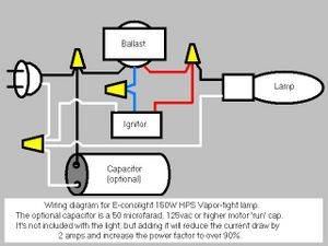
Now because this is a normal power factor ballast it draws quite a lot of current. I measured it at 3.8 amps to start and it settled to about 3.4 amps in a few minutes. This works out to 425 volt-amps of apparent power while the actual power that the lamp and ballast use is 170 watts. I had done a little research and found that a high power factor ballast of this size uses a 52 microfarad capacitor to correct the power factor to over 90% so i had also ordered up a 330v motor run capacitor from eBay of that value. (well, 50 mfd was close enough.) I then connected this cap across the line and neutral of the incoming ac cord, fired up the lamp again and measured the current. I smiled as the new starting current was down from the previous 3.8 amps to a mere 1.75 amps. A couple minutes later it seemed to settle in at 1.4 amps. Now the apparent power is only 175 volt-amps and the true power of the device is rated at 170 watts. This means the capacitor corrected the power factor to 97% and cut 2 amps of current from my wiring.

The power company doesn't charge you extra for those extra amps of reactive power so this won't cut the electric bill, but if your house wiring is as old as mine or you plan on running more than 2 of these on a 15 amp circuit it sure does cut the amps which do nothing but heat up your wires.

So if you want to add this to your project get yourself a 50 microfarad / 125 volt or higher (mine's 330v) motor capacitor and connect it right across the black and white wires entering the box from the outlet in parallel with the whole circuit (see diagram below).

If you are planning on hooking up more than 2 of these lights to a 15 amp circuit, remember that without the capacitor they draw almost 4 amps to start and settle to 3.5 amps. That means that it's only safe to run 3 lamps on a 15 amp circuit. With the cap added to each lamp, your startup current is less than 2 amps per light so you can run up to 6 of them on a 15 amp circuit safely.

Here's a little diagram I whipped up in MS Paint:

 
Last edited:
Hmm... what if you have an extension cord with 2 prongs. Would it still be usable? If so then what would I do with the ground in this case...
 

ambr0sia

Member
free radical said:
Hmm... what if you have an extension cord with 2 prongs. Would it still be usable? If so then what would I do with the ground in this case...

When you're using a grounded extension cord to increase the distance between the socket and ballast, only two of the three wires are used. I just trimmed the extra wire (in this case green/ground) back a bit and made sure it was taped up and insulated off on both ends.


isit4.20yet

Member
The proper thing to do would be to attach the grounds to each other and the cases of each part (box, fixture) of the system.

I could do a diagram that includes all the cases and ground wiring. I just drew the other one up because i felt like doing it.
 
Last edited:
isit4.20yet said:
I just built one of these with the $20 e-conolight. I connected a 4" octagonal box side-by-side with a 'handy box' (surface mountable outlet or switch box). I punched out the middle knock-out of the handy box and a side knock-out of the octagonal box and slipped a romex clamp through the hole to hold them together. I put the ballast in the octagonal box by itself so the heat wouldn't kill the igniter prematurely. i put a romex clamp in the top and bottom knock-outs of the handy box for power in and out to lamp. I test fired this and it worked fine.

Now because this is a normal power factor ballast it draws quite a lot of current. I measured it at 3.8 amps to start and it settled to about 3.4 amps in a few minutes. This works out to 425 volt-amps of apparent power while the actual power that the lamp and ballast use is 170 watts. I had done a little research and found that a high power factor ballast of this size uses a 52 microfarad capacitor to correct the power factor to over 90% so i had also ordered up a 330v motor run capacitor from eBay of that value. (well, 50 mfd was close enough.) I then connected this cap across the line and neutral of the incoming ac cord, fired up the lamp again and measured the current. I smiled as the new starting current was down from the previous 3.8 amps to a mere 1.75 amps. A couple minutes later it seemed to settle in at 1.4 amps. Now the apparent power is only 175 volt-amps and the true power of the device is rated at 170 watts. This means the capacitor corrected the power factor to 97% and cut 2 amps of current from my wiring.

The power company doesn't charge you extra for those extra amps of reactive power so this won't cut the electric bill, but if your house wiring is as old as mine or you plan on running more than 2 of these on a 15 amp circuit it sure does cut the amps which do nothing but heat up your wires.

So if you want to add this to your project get yourself a 50 microfarad / 125 volt or higher (mine's 330v) motor capacitor and connect it right across the black and white wires entering the box from the outlet in parallel with the whole circuit (see diagram below).

If you are planning on hooking up more than 2 of these lights to a 15 amp circuit, remember that without the capacitor they draw almost 4 amps to start and settle to 3.5 amps. That means that it's only safe to run 3 lamps on a 15 amp circuit. With the cap added to each lamp, your startup current is less than 2 amps per light so you can run up to 6 of them on a 15 amp circuit safely.

Here's a little diagram I whipped up in MS Paint:


Could you run 2 150w lights on a cap. like that? Or would it be better to get two caps also? And just curious how much did you pay for your cap?

EDIT- Also more microfarads is better right? I found one on ebay and its 100 uF 370 v ac or 650 dc. Also its oil run, idk if thats bad? Would that do well if I wired both lights to it?
 
Last edited:

RediJedi

New member
Thank you for the feedback, guys. If I followed the wiring instructions on the box of the Vapor Tights would it also work for growing? Just curious.
 

Quazi

Member
There are no instructions on the box for this unit. It just comes with everything in a housing above the lamp itself with the white, black and ground wires sticking out. In fact, I don't recall there being any wiring documentation included with this unit.

That's why this thread was created :wink:

-Q :rasta:
 

AP KUSH

Member
Hey Quazi,
Thanks for this awesome DIY thread... very inspiring. I also want to thank isit4.20yet for his wiring diagram. I didnt use a capacitor to rig up mine, but it still works fine and as it would be, im on a tight budget.

Anyway thanks again guys
 

Latest posts

Latest posts

Top