What's new
  • Happy Birthday ICMag! Been 20 years since Gypsy Nirvana created the forum! We are celebrating with a 4/20 Giveaway and by launching a new Patreon tier called "420club". You can read more here.
  • Important notice: ICMag's T.O.U. has been updated. Please review it here. For your convenience, it is also available in the main forum menu, under 'Quick Links"!

Growroom Electricity and Wiring

PharmaCan

Active member
Veteran
PharmaCan - Hey thanks a lot. I suppose I should match the gauge of the wire in the "power strip" to the gauge of the wiring to the receptacle (at least) or do you recommend something.

Dr. Conjuror

I always used 12ga. wire for the cord and the wires to the receptacles.

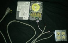
Any sparkys around?I did see a diagram for wiring 2 240 outlets using the pigtail method but how to do 4?Just add to that pigtail?Please show me!!!!

Well, assuming that you have the proper size wire and the proper size circuit, then, yeah, you can just add more pigtails. You're probably coming in with 10ga. wire so, take four pieces of 12ga. wire and wire nut them on to each hot leg then run two hots, one from each leg, to each receptacle. Do the same with your ground. ...I guess that's what you're asking.

PC
 

Danknuggler

Active member
I always used 12ga. wire for the cord and the wires to the receptacles.


Well, assuming that you have the proper size wire and the proper size circuit, then, yeah, you can just add more pigtails. You're probably coming in with 10ga. wire so, take four pieces of 12ga. wire and wire nut them on to each hot leg then run two hots, one from each leg, to each receptacle. Do the same with your ground. ...I guess that's what you're asking.

PC
Coming into the timer will be either 10ga or a dryer plug.What I need to see is a wiring diagram for 4 240v simplex outlets coming out of that timer.First off I'm confused why you are telling me to use 12 ga.I have a WH40 timer.I still dont understand your wiring explanation.I need to see some kind of diagram.
 

Danknuggler

Active member
This is what I would like to build.I already have 2 "little grey box"es.Where can I get those 240v duplexs at??And then how to wire that???Anybody have pics with the receptacle opened up?I honestly cant believe there isnt a Sticky in the DIY section on these controllers.
 

Attachments

  • lightswh40.jpg
    lightswh40.jpg
    36.8 KB · Views: 24

Danknuggler

Active member
This is what I would like to build.I already have 2 "little grey box"es.Where can I get those 240v duplexs at??And then how to wire that???Anybody have pics with the receptacle opened up?I honestly cant believe there isnt a Sticky in the DIY section on these controllers.
BUMP
 

PharmaCan

Active member
Veteran
Coming into the timer will be either 10ga or a dryer plug.What I need to see is a wiring diagram for 4 240v simplex outlets coming out of that timer.First off I'm confused why you are telling me to use 12 ga.I have a WH40 timer.I still dont understand your wiring explanation.I need to see some kind of diagram.

Sorry - I have no way to make a drawing.

PC
 

Danknuggler

Active member
Anyone?Look I can wire shit.Just explain like red wire goes here,black goes there you know real easy like?I dont know sparky terms.Hot leg?? OK I have a 30 amp double pole in the box and 10ga going from the box into a WH40.From the WH 40,please explain in the easiest terms possible how to wire 4 240 v outlets.Or better yet where to get the 240v duplex's as I posted above as I think those would work out better.But if I cant get those duplex as I cant find them at home depot at all only the single outlet 240v then thats what I'll have to use but still couldnt really understand your direction you gave me and still dont know why you say to use 12 ga on a 30amp line?Was that a typo or what?Please explain?
 

cocktail frank

Ubiquitous
Mentor
ICMag Donor
Veteran
take the ground wire off the 30A cord and ground it to the timer case via the ground screw on the clock face.
that leaves you w/ 2 wires left on the cord.
there will be 2 screws marked "line" on the plastic screws cover.
put 1 wire under each screw on the clock.
that takes care of the power side of the clock.

take your wire going to your 240v receptacles and ground the ground wire to the same ground screw the power side ground went to.
then take one wire and place under each "load" screw.

now your clock is wired.
i would recommend using the appropriate connector when attaching the line/load wires to the clock.
i'd use a 3/4" rx connector for the dryer cord.
Romex-Connector.jpg


then whatever wire you use to run to your receptacles, use the right connector.
rx conn for romex
bx conn for metal wires (mc, bx, ac, etc)

finding duplex receptacles rated for 240v can be a chore.
your best bet might be to buy 4 single receptacles @ 240v.
you could always gang up a set of singles into 2 boxes to make life easier.

tech speaking, the most your gonna run off any single 240v outlet is most likely a 1k.
thats about 4.5A @ 240v.
you could even make your pigtails 14 awg if it makes it easier to splice all those together for ya.
but thats only for each single receptacle.
you still want to run 10awg's from the clock to your splice point.

unless, you plan on putting the plugs right next to the clock.
if u used an offset/ shoulder nipple, you could just sleeve the 14's thru the nipple and put em all right onto the load screws of the clock.
you got options, depending on how you go about it.
hope i helped
 

madpenguin

Member
If all this is going to be fed by a 30A double Pole breaker, then ALL wiring to point of terminations need to be atleast 10 AWG. No splicing to #12 or even to #14 for your receptacle conections. Othersise it's no longer a 30A circuit but now rated for the smallest wire that you are using.

I'm not entirely sure they make a NEMA 6-30R duplex receptacle. What you would have to do is buy a 4 gang box and use 4 single 6-30r's or how many you ever need. It all has to be #10AWG tho, otherwise you need to bump the breaker down to the rating of the smallest conductor.

Not sure I like all this talk about #12 and #14 on a 30A breaker.........
 

Danknuggler

Active member
Thanks Frank that does help some.Yes I am going to mount the receptacles right next to the timer just like in the pic above.What I need to see is how to actually wire all 4 receptacles.I know how to wire a single 240v as I just wired a 220v line for an ac unit.,but I dont know how to actually wire 4 receptacle like in the pic and how to make a box that hold all 4 like in the pic I posted.Yes thanks Madpenguin.I am using ALL 10 ga I dont know why anyone would go smaller???Please anybody able to somehow show me or in very simple terms tell me how to wire all 4 240v receptacles into a 4 gang box.Thanks for the help .
 

madpenguin

Member
I just bought 2 WH40's for 20$ each @ home depot they are changing over to GE so they were on clearance.I want to run 4 1k's per timer.I looked for 240 volt duplexes but couldnt find those, only a 240 v simplex.I take it they dont make a 240 duplex?Can someone show me wiring diagram for 4 240v simplex coming from my WH40 please?Thanks

picture.php


Looks pretty easy to me. 10/2 with ground on a 30A double pole breaker in your main panel. Put a black piece of tape around the white wire that attaches to the 30A breaker. Both black and white wires will attach to the 30A DP breaker in the main panel. Attach the bare ground wire to the neutral/grounding bus terminal in the main panel.

If you have exposed joists in the basement, use a 3/4" auger bit to drill thru the joists. Drill right through the center of the joist with relation to top and bottom. Also, try to stay near a concrete wall. Try not to drill through the middle third span wise of a joist if that makes sense. These holes are to fish your 10/2 with ground through. Buy a piece of grey electrical conduit at Home Depot. Once you want to take the 10/2 down the side of the basement concrete wall, attach the grey electrical conduit to the wall with masonry screws and 1/2" pipe clamps to secure the electrical conduit. Just push your 10/2 down the conduit until it comes out the bottom. Looks like there is a knockout on the side of the timer. Buy a white plumbing elbow or something to mate with the electrical conduit so you can run the 10/2 into the timer so no cable is exposed. Mount the timer to the concrete wall with masonry screws as well.

With me so far? Everything securely fastened.... Take your incoming black wire and attach it to terminal 1. Take your incoming white wire and attach it to terminal 3. Take the incoming bare wire and attach it to the ground screw. Put a piece of black electrical tape arond the white wire in the timer box.

Buy some MC cable that has 10/2 with ground. Run it out of another knockout in the timer box. The green sheathed wire attaches to the grounding screw. The black wire attaches to terminal 2. The white wire (put a piece of black tape around it) attaches to terminal 4.

Take this length of 10/2 MC (Metal Clad) cable and run it how ever far you need to get it to where you want your receptacles. Buy a quad gang box.
picture.php


Try to use the metal ones. Take the MC cable through one of the middle knockouts. Unless your really skilled with a hack saw, you'll want to buy some MC cable cutters.

picture.php


The roll of MC you bought should come with redheads (anti-short bushings). Cut enoungh of the jacket off the MC so you have atleast a foot of conductors sticking in the quad metal box. Use a metal NM connector to securely fasten the MC cable to the metal box.

picture.php


So once you install the redhead into your freshly cut MC cable (to protect the inside conductors from getting damaged on the rough cut edges of your MC outer sheathing, tighten down the NM connector until the MC cable is held securely in place.

Now you have about 12" of green, black and white conductors in the quad metal box with about 3/8" of MC cable jacket entering the box. Get a green grounding screw. These can be had at Lowes or Home depot as well.

picture.php


Strip atleast 6 inches of the green insulation off until your left with bare copper conductor. Find a hole in the quad metal box that one of those green grounding screws fit into. Start threading it just a couple turns so it stays. Take your stripped green insulated conductor and wrap it around the grounding screw paying close attention that when you tighten the grounding screw down all the way, it will pull the bare conductor tight and not squeeze it out. Once the green grounding screw is really torqued down, You should have bought atleast 4 grounding leads from Home depot or lowes as well.

picture.php


Actually, forget about buying the grounding screws separate because we can use the ones that come with the pigtails. Whatever few inch piece of bare copper is left from when you tightened down the grounding screw, take a pair of linemans pliers and mechanically twist all the grounds together. Then wirenut 4 of the above grounding pigtails to the bare copper conductor that is attached to the back of your box. You'll need the big blue wirenuts for this. When your using linemans pliers to mechanically twist wire together, use very little force at first. Kind of let the wire slip through the plier heads. With each turn of the wrist, put more pressure on the bare copper wire that your trying to twist. You will eventually get all of the ends of wires to line up with each other and it will look like(and be) a really nice electrical connection. If you just really clamp down on all the wires at once and then twist really hard, wires will slip out and it'll look like shit and you'll have to do it over again. Sounds silly but there actually is a correct way to twist wires together. You'll figure it out.

Cut about a foot piece off of any left over 10/2 with ground romex and get the black and white conductors out of it. Put black pieces of tape around 4 white wires and then you should also have 4 black wires. Wire nut all the blacks together (including your incoming black lead from the timer box). Do the same with the white wires but make sure each white wire has a piece of black electrical tape around it.

Now you have 4 black wires, 4 white wires and 4 green wires inside your quad gang metal box.

Need I continue?

These are 240v receptacles. Put a black on one side and a white on the other and then a green on the grounding screw of the receptacle. Do that for all 4 receptacles, then find a metal box cover that will work with your receptacles. If there are any plastic round or square thing-a-ma-bobs holding the mounting screw for the receptacle in place, remove those. You want metal on metal contack with the yoke(strap) of the receptacle to the metal of the box.
 

madpenguin

Member
BTW, try to get most of this stuff from a local electric supply house unless ofcourse it's cheaper at Lowes or Home Depot.

Have I ever seen 10/2 w/ ground MC cable at Lowes? Dunno. The only reason I suggested MC cable is that I have a feeling your just going to have your wire laying all over the place such as on the ground.

Remember romex can not be exposed to physical damage. Make sure you fish that stuff through the cieling joists of your basement and then sleeve it with EMT (Electric Metalic Tubing) or the gray Electrical tubing you see at Lowes. Romex is VERY subject to damage. We had an arguement on whether or not to use NM connectors a day or so ago with NM and the answer is an EMPHATIC YES! That sheathing will get damaged if you just breathe on it wrong.
 

PharmaCan

Active member
Veteran
Madpenguin - I'm not going to argue code with you, since I'd lose, but... As far as using #12 or #14 for the final few inches (the pig-tails) that go to the receptacles, there's nothing wrong with that. You're not trying to pull 30 amps per receptacle for crying out loud, only 5. Think about it this way - the receptacle box he is making is basically an appliance and the internal wiring of the appliance doesn't have to follow the same rules as the circuitry bringing the power to the appliance. We could pick nits all day long about how to define the four gang box and its contents, but I think you get my point. 10 ga. wire just isn't necessary for the pigtails and would make the wiring a lot more difficult.

Trying to do all that wiring in a little bitty box with all #10 wire would be a major PITA that simply isn't necessary.

Danknuggler - you are going to be running a piece of cable from your timer to your receptacle box. Inside that cable are 3 #10 wires - Black, white and bare (or green). Each of those wires is called a leg. The black and white legs are hot, the bare/green is a ground. To each of those three #10 wires you need to attach (wire nut) four more wires. Those wires are called pig-tails. Each pig-tail goes to a receptacle. You can make those pig-tails out of #12 or #14 wire, either one is sufficient to carry the load you envision. Trying to make all of those pig-tails out of #10 wire and then trying to stuff everything into the four gang box would be very difficult, and foolish, especially since there is no good reason to use such big wire for your terminal connections.

PC
 

overbudjet

Active member
Veteran
Hi MADPENGUIN may i use s.s.r.(solid state relay )instead of using mecanical one for switching HPS.
In 120 volt i know i have to open the hot wire (black)but with 240v 2 hot wire do i need 2 s.s.r. ? S.S.R. will be rated at 40 amp at 240v. with cooler . i will drive 2 1000 watts ballast.

bump.
 

PharmaCan

Active member
Veteran
Make sure you fish that stuff through the cieling joists of your basement and then sleeve it with EMT (Electric Metalic Tubing) or the gray Electrical tubing you see at Lowes. Romex is VERY subject to damage.

WTF - Did you join the Get Ugly Early Club? Wake and Bake? Get your brains fucked out last night? WTF is this supposed to mean - in English. LOL

We had an arguement on whether or not to use NM connectors a day or so ago with NM and the answer is an EMPHATIC YES! That sheathing will get damaged if you just breathe on it wrong.

ROFL - That poor guy ran home to mommy. Too bad - except for that one connector it was a pretty good diy. But, man, that dude took every word of the discussion personally, even after we told him not to. I had to laugh when he deleted the whole damn diy.

PC
 

cocktail frank

Ubiquitous
Mentor
ICMag Donor
Veteran
i'm still gonna say the 14/12 jumpers are ok.
only because, as stated earlier, each 240v receptacle will not draw over 4.5amps.

how many times has any electrician fed a machine with a large line, only to have the guts of that machine run its factory wiring w/ smaller size wires than the feed line?
most of the time, the controls and inner working of a machine have ocp on the factory wiring, but not always.
this would be no different.

also, using nothing but 30-r's is redundant. not to mention ganging them up in a box is not gonna happen.
i feel like my advice was sound and correct.
i've only been a licensed electrician for a handful of years, but i been doing this work since last century!
 

PharmaCan

Active member
Veteran
i've only been a licensed electrician for a handful of years, but i been doing this work since last century!

ROFLMAO - it takes a certain way with words to make ten years sound like a real long time. But why stop with last century? You've been doing this since the last millennium! No need to be modest. LOL

PC
 

madpenguin

Member
madpenguin said:
Make sure you fish that stuff through the cieling joists of your basement and then sleeve it with EMT (Electric Metalic Tubing) or the gray Electrical tubing you see at Lowes. Romex is VERY subject to damage.

WTF - Did you join the Get Ugly Early Club? Wake and Bake? Get your brains fucked out last night? WTF is this supposed to mean - in English. LOL
PC

I'm confused. I'm talking about his 10/2 homerun from the panel to the WH40 timer. ALL romex has to be protected from physical damage. You can only staple a 6/2 or 8/3 to the bottom of ceiling joists. Anything smaller has to be ran thru holes. 10/2 is certainly smaller than 8/3 or 6/2....

PC and Cocktail frank, you are overlooking something extremely important that should have been learned by any first year apprentice. They are called Articles 210.20(B) and 240.4. If you guys do any electrical work on a regular basis, I strongly suggest you familiarize yourself with the NEC. Besides the below articles, common sense would tell ANYONE that you need to use the same gauge throughout the entire circuit.

210.20 Overcurrent Protection.

(B) Conductor Protection. Conductors shall be protected in accordance 240.4. Flexible cords and fixture wires shall be protected in accordance with 240.5

240.4 Protection of Conductors. Conductors, other than flexible cords, flexible cables, and fixture wires, shall be protected against overcurrent in accordance with their ampacities specified in 310.15, unless otherwise permitted or required in 240.4(A) through (G).

240.4(D)(3) 14 AWG Copper. 15 Amperes.

240.4(D)(5) 12 AWG Copper. 20 Amperes

So....... Again. Tell me why it is OK to use #12 or #14 pigtails coming off the #10 homerun to attach to your receptacles? Common sense will tell you you'll have an instant fire if that receptacle see's more than 15A if it's using a 30A 0CPD.

I'm sorry but this is childs stuff that even the original poster knew and he's not even an electrician to my knowledge. What's your guy's excuse?

I'm still gonna say you guys are DEAD wrong and anyone who listens to you runs the risk of burning their house down.
 

madpenguin

Member
the receptacle box he is making is basically an appliance and the internal wiring of the appliance doesn't have to follow the same rules as the circuitry bringing the power to the appliance.
PC

Oh..... PC..... You fail. It absolutely must as a dare I repeat the phrase be "a minimum safety standard". This is what the NEC is. Since when do we get to choose what parts of the NEC to follow and what parts we don't want to?

Not insulting anyone here, but that it a time saver technique and and the sign of a hack electrician, not to mention you'll burn someone's house down.
 

FreezerBoy

Was blind but now IC Puckbunny in Training
Veteran
Here you go Sleepy. Stickified just for you.
:woohoo:

Now gimme some magic cowbell!
 

Latest posts

Latest posts

Top