Hatery1967
New member
Perhaps you could use a pressure differential switch. An old combi boiler would provide one.

This one has adjustment, but the outline shape makes them recognisable. It's job is to see the fan is running. In function, there is a diaphragm at the widest part. A cavity below and above it, each have a 4mm? pipe spigot, visible in white and grey here. The white one, connects to the fan at the inlet side. The fan sucks the diaphragm upwards. The grey connects to the outlet of the fan, to assist this movement with some push. The physical orientation of this device can alter the pressure needed to switch it. As can the adjustment. Extra vacuum can be found by taking that vac pipe into the air stream, pointing it downstream, and even flaring it out a little. Or a little venturi action, by narrowing the inlet just before the fan.
I recently fitted a 30w 7" pc fan into a case, using one to detect the fan is running. No effort. Just one pipe in the case, one pipe outside. The case was not sealed, or the fan that great. These are remarkably effective, and should have no problem sensing your tube fan. Offering enough sensitivity to even choose the run speed you want to switch at.
The contacts are spdt.
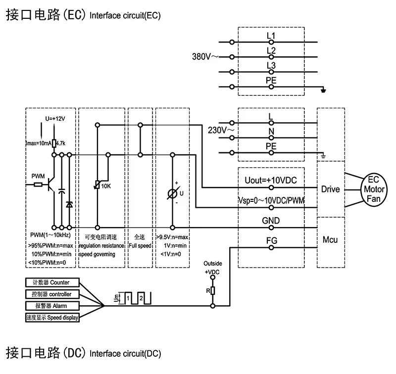
Thanks for the controller info. It's good to know. I really don't want to be drawing out heat, at the expense of RH. Though I'm tempted by the 69s VPD tracking, and duel zone, the 67 seems like all I need. I think the 69 even controls LED lights, which are another 0-10v or pwm device. Stock levels here n there, suggest the 67 may of even been superseded by the 69. One supplier just sold out cheap. Real cheap.
")