
You are using an out of date browser. It may not display this or other websites correctly.
You should upgrade or use an alternative browser.
You should upgrade or use an alternative browser.
Building a Home Made LED
- Thread starter tenthirty
- Start date
cimenk_hel
Member
@PetFlora when you say you are using nw:ww at 1:6, do you mean some kind of ready-made bulbs? In a previous comment I understood you are talking about cree leds, such as xm-l.
^^ Ready mades. I don't have the equipment to build my own. See the picture in post 639
Since adding the 22w and rearranging bulb positions so that the 5000K is in the center with 2 RP WWs on either side they are growing before my eyes. In fact they are so much bigger this morning than yesterday.
Examining the ratio: 2 WW (3000K) bulbs totaling ~2000 lumens + 6.5w of 5000K totaling 490 lumens (with globe removed) 490/2000=~ 25% NW:WW, Keep in mind the WW bulbs have some blue in them, and since they are RP (remote phosphor) the globes cannot be removed
View attachment 208419 View attachment 208420
I'm going to start laying out the LEDs on the Sink and I want to take every precaution for static.
I have a wrist ground with the slinky and alligator clip. I have an anti-static mat with the same grounded slinky wire.
Per Rive's great idea, I'll make a plug for an outlet and only run the ground wire. I'll connect both the wrist ground and the mat ground to this outlet ground.
Anything else I should do? Connect the sink itself to such a ground?
Grounding the sink would give you a nice grounded work area. You are striving to keep the work area grounded - anything that could possibly store or transmit a charge to the chips.
Xm, I'm too lazy to go back and look - what driver are you using on the string that blew? It sounds to me like there might possibly have been some start-up drift on the driver current limiting. If you were already at the maximum the reds could handle.... If you have a meter with a storage or "peak" function, it might be interesting to check what that driver does upon power-up.
Xm, I'm too lazy to go back and look - what driver are you using on the string that blew? It sounds to me like there might possibly have been some start-up drift on the driver current limiting. If you were already at the maximum the reds could handle.... If you have a meter with a storage or "peak" function, it might be interesting to check what that driver does upon power-up.
what driver
meanwell apc-16-700
24v .7A
cant help but think some of this is just that red LEDs arent as 'tough' as blues
also; something i have noticed is with these self-fab'd heatsinks; they probably arent as efficient as a purpose-built profile anyway but; they also need to run the way they are 'designed' to wrok
when i had the 'event' the heatsink was 'upside-down' {lights up} AND; of course - the heatsink is virtually out of the equation if the heat isn't transferring 'up' into it
i ran the crees for a few moments 'upside down' and they heat up significantly {get hot to the touch} pretty fast ~once i turned it over and ran it {right-side up;} they warm up and level off @ warm but not hot to the touch
i know; i really need a laser thermometer
not willing to disregard heat as a component in the 'event'
We'd sure appreciate if you kept an eye on this and let us know. Very interesting.
I'm curious what the distance is from that plant's meristem to the nearest LED above vs. the side. Might the lenses you have on the overhead unit be creating a slight dead spot from above, making the side LED the brighter source for that one plant top?
The top that shown heliotropism has grown to tall (above the lights) ans now it shows some heat stress signs being to close to the heatsinks. I did not observed any tendencies to turn it's head for the light, but the leaves on it are twisted toward the LEDs.
Hello everyone,
i'm in the process of creating a DIY LED Panel right now and have found some components i want to use and i want to ask you whether it will work.
My Growbox is a PC Case, the measures are 15' x 7.5' x 24' (lwh).
I want to bild a panel for both veg and flower.
LEDs:
OSRAM GD+
16x hyper red/656 nm @525 mA (2.25V)
5x warm white @525mA (3.35V)
3x deep blue/455 nm @ 525mA (3.35V)
For the current-source i want to use the MW LPC-60-1050: 50W / 9-48V / 1050mA
I want to put two strands parallel and in each strand 8 red and 4 white/blue LEDs in series. In this mode the current should divide equally into the both strands, shouldn't it?
With this wiring there should be about 31 V over the strands and the LEDs would need ~33W altogether.
Are my calculations correct and will it work or is there a need for optimization?
tenthirty
Member
The formulas are absolute, The real world is not.
Using leds as a voltage divider is probably a bad idea.
You are counting on all the leds working, if a string fails????
The driver is going to push 1050mA no matter what the voltage may be withing the range of the driver.
It is recommended that each driver only support a single series string.
Using leds as a voltage divider is probably a bad idea.
You are counting on all the leds working, if a string fails????
The driver is going to push 1050mA no matter what the voltage may be withing the range of the driver.
It is recommended that each driver only support a single series string.
2cent13adz
New member
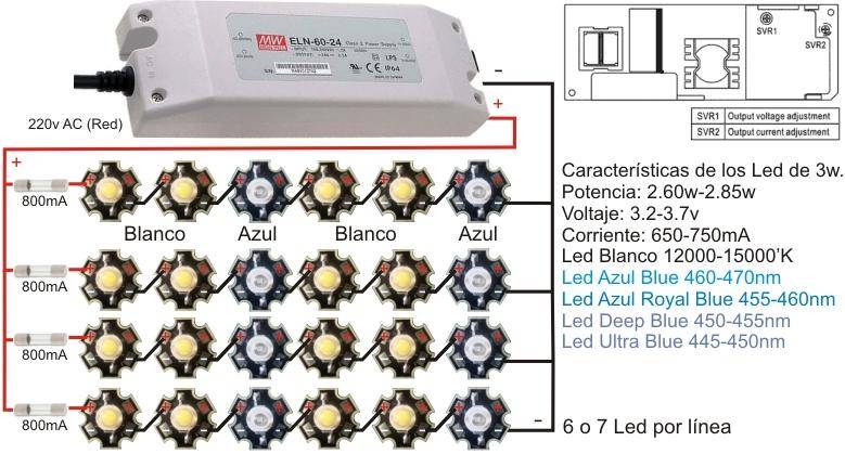
Different voices give contradicting advice at times. My experience is 1 driver/multiple strings works just fine. Me obviously beeing just another voice from the web, don't trust me. You may want to take a look at what some of the guys selling this stuff say. This random example is from shoptronica (please note the fuse):
Peace!
Peace!
As 10:30 said, it will work perfectly, until something wrong happens on a string.
When a chain fails, the surplus current will be divided to the remaining functional chains
If the current on a chain is X mA and we have N chains, the surplus current will be Xma/(N-1) . The remaining LED chains will be driven then not at XmA, but on X+X/(N-1).
With real numbers this means :
- for 4 strings of LEDs running each at 700mA, we have a total curent of 2800mA . The driver will 'froce' the connected circuit to run at 2800mA increasing the voltage on the output until the 2800mA limit is reached.
- when a string fails, the current stop traversing it so we will have an overhead of 700/(4-1)=233mA , which means that the remaining 3 LED chains will be forced at 933mA.
- if the fuses are fast enough (but as 10:30 said - the fuses are slower than diodes) they will burn out . The first fuse to fail will cause a double current on the remains LEDs and so on.
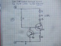
With little investment, this circuit can be protected to work without any problems even when one or more LED chains fails. The protection can be build with a cheap MOSFET transistor (ex BUZ11), a NPN transistor (ex BC547) , a 10-100KOhm resistor and a 0.85Ohm/1W resistor.

When a chain fails, the surplus current will be divided to the remaining functional chains
If the current on a chain is X mA and we have N chains, the surplus current will be Xma/(N-1) . The remaining LED chains will be driven then not at XmA, but on X+X/(N-1).
With real numbers this means :
- for 4 strings of LEDs running each at 700mA, we have a total curent of 2800mA . The driver will 'froce' the connected circuit to run at 2800mA increasing the voltage on the output until the 2800mA limit is reached.
- when a string fails, the current stop traversing it so we will have an overhead of 700/(4-1)=233mA , which means that the remaining 3 LED chains will be forced at 933mA.
- if the fuses are fast enough (but as 10:30 said - the fuses are slower than diodes) they will burn out . The first fuse to fail will cause a double current on the remains LEDs and so on.
With little investment, this circuit can be protected to work without any problems even when one or more LED chains fails. The protection can be build with a cheap MOSFET transistor (ex BUZ11), a NPN transistor (ex BC547) , a 10-100KOhm resistor and a 0.85Ohm/1W resistor.
Attachments
2cent13adz
New member
"A diode is "usually" a better fuse than a fuse."
This is interesting. Wague memory of a discussion about that somewhere (here?). Someone argued this a reason not to bother with fuses, no? Didn't see the end of it, was there any testing done? Not saying it can't happen, would like to know under what conditions it does.
Keeping drivercount low is one way of simplifying things to me, but maybe not worth it if introducing other serious problems.
-----------------
adding after reading hemp's post:
So what it boils down to, in the pic above, is if the fuse is fast enough? If you know of anyone testing this, please point me there. For the record hemp, I do like your easy solution for additional protection, but if 'fast' fuse is enough, so much the better.
I'll put this on my evergrowing list of tests I'm gonna do when there is time...
what would be sweet is micro driver ran diodes that are all inclusive
no strings involved
no strings involved
I don't know that an LED is a "better" fuse than a fuse, but they are sure as hell faster under most conditions. Blow the chip to save the fuse....
IF you feel compelled to run parallel strings, I would use fast blow fuses and make sure that the diode's maximum allowable current is equal to or greater than the total driver current ie - Driver sources 3 amps, LEDs capable of 3 amps, drive three parallel strings @ 1 amp, fuse @ 1.25 amp. Even with inadequate cooling, the chips can withstand the 1.5-3 amps that they will receive if one or two strings blow until the fuse can react. Hempfield's approach of using a current limiting circuit between the driver and the string is also a viable option. I don't think that skyslimit's circuit has much of a chance of being evenly balanced with an odd number of different colors divided up into an even number of parallel strings.
I prefer one driver > one series string for simplicity and flexibility wherever it is feasible.
might be a good idea to organize some caveats
protect your eyes
under-drive for reliability >you dont have to but a little margin for error
match rated diodes to a string >may or may not matter?
1 string per driver> again not necessary but leads to more consistent reliability and scales down failure
you know stuff like that
sort of uh; 'you know you can bla-bla-bla but; if you want reliability; bla-bla-bla'
cimenk_hel
Member
I'm coming across lots of different information about heatsinks. I'm trying to figure out how much heat my heatsinks can dissipate. Dimensions are 250mm (L), 30mm (D), 40mm (H). It has 27 fins so that the surface onto which leds would go is 250 by 30.
It seems that many recommendations fall between 5 and 10 square inches per watt. But I'm having a hard time figuring out what I should take as the useful surface area of the heatsink!
I'd like to put 6 xml on there, at about 5w each, perhaps a bit less. Light fan cooling. Any known guidelines for my calculations?

