What's new

New grower, introduction and questions.

Hey guys, pleased to be involved in this place. I've been checking here and OG (when it was still alive) for a while but have finally now gained the space to do a small grow. I have 3 seeds recently hatched in solo cups with 2 lowryders and 1 mp5k. Right now as they are in their beginning stages I'm using 2 42watt cfls but they're soft white so I don't know if thats going to cut it at all, especially when these get bigger. I may have a male in one of the lowryders. Only a few days in and he's pretty tall and lanky but I haven't read up on the correct ways to identify these things yet. I would love to go with mh or hps but from what I understand, these applications generate more heat than cfls, so for now its cfls. I did find a specified "plant light" that is made by phillips and sold at home depot though... Anyone had experience with these? They have a blue color and are named agro lights, it sounds perfect but if it would be a waste then I don't want to bother.
Also, would anyone know in which section of home depot the foil reflective sheeting would be located? I'd rather not draw any attention at all so thats why I ask.
Has anyone bred a lowryder x mp5k? I could imagine the new strain "driveby".
I'm doing a lot of learning currently, sorry for the rather basic and senseless questions, I'm just excited about my first endeavor.
(oops, meant to post in the main area)
 
Last edited:

pieceofmyheart

Active member
Veteran
Hello and welcome to IC and Micro grows, there is a wealth of info in here. Many of us have grown and are still growing with cfls. MajPothead always come to mind, check out his thread, he talks a lot about cfl's.
The reflectics material is in the insulation section, I couldn't find it at Home depot though, found it at Lowes.

I have grown lowriders, am growing 2 right now. I am not good enough to tell if it is male or female till it shows signs of sex. I always have to wait.

Good luck with everything and we are always here to help.
 

duggy

Member
Actually, watt for watt, HPS will be cooler than CFL. Get yourself a 70Watt HPS (Home Depot, 60 bucks or so). Don't buy any 'plant' lights.

gr
duggy :smoker:
 
do they sell the ballasts for the hps lights as well at home depot? I looked but had no luck. It isn't very hot right now with 84 cfl watts total going through.
Thanks for the welcome.
 
They have those flood lights at home depot as well but as soon as I saw that they didn't come with a plug already attatched, I backed off. With no electrical knowledge, I don't want to risk something like a short and then a fire.
 
R

Reinhold

yeah POMH thatd be sweet if you could find some info on that cause I'd like to know too. peace.
 

Mr_Micro

Member
I as well have wired up some of those 70 watt e-conolights and I can tell you that it is incredibly simple. I have zero experiance in anything electrical (outside of this wiring project) but I can assure you that as long as you can tell the difference between a white and a black wire then you have nothing to worry about. :biglaugh:

Heres a little guide with pictures to wiring up the light http://www.drugs-forum.com/growfaq/1151.htm
However you should know that it will be a lot easier than described in this guide. First off, the E-conolights do not come with a photo-sensor built in, so you won't have to worry about cutting and reconnecting those wires.

Also, instead of using the Radio Shack project box the guide shows I recommend using a 4"x4" junction box from Home Depot to hold the ballast assembly. It's pre-drilled for the rommex connectors so you won't need a drill for the project.

I did this whole project with a pair of pliers, a few screw drivers, and a pair of wire snips. I was also able to get all the parts at home depot.

It might look a little complicated but trust me on this one, it is extremely easy even for someone with zero electrical experiance. :D
 
Last edited:

mtnjohn

Active member
Veteran
mr micro is right on the money , any light setup is pretty much common sense to rewire, very easy
if you think you might have trouble then tag all the wires with masking tape and letters or numbers so that when you disconnect them all you have to do is match wire A to wire A and connect them. wire b to wire b and connect , i hope i'm clear enough to understand.

also remember to properly ground the fixture
and good luck mj
 

pieceofmyheart

Active member
Veteran
hahahahaha I guess I meant more detailed instructions....you said that like to someone who has done electrical stuff before.

Ok I tagged them all...now what do I do with them????? Put them in the ground you say?
 

imnotcrazy

There is ALWAYS meaning to my madness ®
Veteran
A 120V ballast is extremely easy to remove from a light housing and rewire as a remote ballast, just cut and extend one wire at a time and it should be extremly difficult to mak any mistakes. As for the plug hookup, that's straightfoward also.
 
awesome, this assistance is much appreciated guys, now I can think of some new ways to work with my cab. I have a 7' clip on fan blowing around in there but I'm starting to feel like ditching the cab altogether and just using the spot in the closet that the cab is sitting in. Only problem is light proofing because I know that light is going to drive me crazy at night.
Alright guys, off to pick up some 2-3 gallon buckets, thanks again for the help.
Edit - I think I'll decide to get a 150hps from bettergrowhydro.com, they just look like very nice setups.
 
Last edited:

Mr_Micro

Member
Okay... well, I was hoping to avoid having to write out detailed instructions for this, but I'll do my best to explain it without making it seem too complicated. This guide is very long, but it is not complicated. I have made sure to explain every little step in good detail so even someone with no electrical knowlege at all and no power tools can safely and easily remote ballast their light as long as they have a little patience. The total cost of this light will be around $50 to $60 or so I think. Just gather the supplies listed and follow the instructions and you should have no problem putting together your own grow light.


(Disclaimer : These instructions worked very well for me, but I will not be held liable for any damage to yourself or your property in that may occur in the creation of your remote ballasted light. Although I consider this project to be completely safe in every way if the instructions are followed correctly, you should still use at your own risk.)


First off, heres the tools your going to need.
===========================

A pair of pliers with a sharp edge to cut wire and cables
A pair of needle nose or similar pliers to hold screws in place while you tighten them down
A small selection of phillips head screw drivers
A small pair of scissors.
A wire stripping tool (optional... you can strip the wires with your pliers if your careful)


And now for the parts you'll need...
======================

One 70 or 150 watt HPS or MH security light of your choice (best deal from e-conolight.com)

One electrical box and box plate (3"-4") from Home Depot. (This will be used to mount the light socket to)

One 4"x4" or larger junction box and box plate from Home Depot. (This will be used to house the ballast and components, and can be found in the same section as the electrical box)

One medium or heavy duty 25 ft. extension cord (The 3 prong orange kind, can be found at Home Depot as well)

One medium or heavy duty grounded male electrical plug end (One of those orange 3 prong ends that can be wired to an extension cord)

Three Romex cable connectors (Should be near the Electrical Boxes & Junction boxes)

One box of wire nuts (They will be used to connect the wires together when you re-wire the light and ballast. You'll need 6 of em I think)

A bunch of #6 sized nuts, bolts, and washers. (You'll need three 1/2" or 3/4" long bolts, and five nuts, and 10 or so washers. Buy extras just to be safe)

Also, if you wish to use the original reflector that came with the light, you should pick up an extra set of #6 bolts, nuts, and 2 more washers along with a set of larger sized nuts/bolts/washers and a coil of pre-drilled bendable metal stripping from the plumbing department. More on this later...


Now that your done shopping, heres what you do with all the stuff.

The first thing we're going to do is remove the components from the light. I personally like the lights from e-conolight.com because they don't come with a built in photo-sensor like the Home Depot lights. The photo-sensor is what causes the light to come on at night and shut off in the morning. Buying a light without a photo-sensor built in will save you from having to remove the sensor and re-wire the ballast, as well as save you a bit of cash.

But where were we... ah yes, removing the guts from your new light. This guide was written based off this light, but I'm pretty sure it would apply to most any of the e-cono lights.

The first thing you do is flip the little hinge on the side of the light and open it up. Then take your phillips head screwdriver and remove the screws that hold the light socket and releflector in place. You probabably won't need those screws again, but set them aside just in case.

When you lift out the reflector you will notice there is a strip of metal holding down the ballast with two screws. Remove those screws and the metal strip as well.

Now that you've removed those, take a look at the side of the light with the little handle coming out of it you should see white, black, and copper wires running out of it. Loosen the screw on the side of the handle thing pull the white and black wire out of the handle to the point that you have a good 5 or 6 inches of white and black wire between the ballast and the handle thing. You can then take your wire cutting pliers and snip the white and black wires (just make sure you have 5" or so of wire left coming out of the ballast assembly. Don't worry about that copper wire, you won't need it.


You may now remove the ballast and light socket assembly from the inside of the case and place it on a clean dry work surface ( I just put it on my floor to be honest :tongue: ). What you should have now is the ceramic light socket attached to a peice of metal with some white and black wires running out of it, which is connected to a whole jumble of wires connected together with wire nuts, which connects to a little white rectangle or black cylinder thing (the ignitor) and a heavy metal box type thing (the ballast) with some white and black wires running out of the jumble.
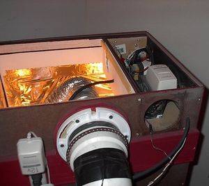
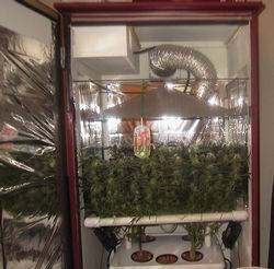
This may sound a bit complicated, but trust me on this one. You will not need to remove any of the wire nuts from that jumble of wires. The only wires you will be concerning yourself with in this project are the white and black ones (and the green ones coming out of your extension cord eventually).


So now that we have the guts from our light removed, lets start by wiring up the remote ballast. You will notice a small length of (usually fabric coated) white and black wiring running from the ballast assembly to the light socket. Cut these white and black wires in the middle to seperate the light socket from the ballast assembly. Set the ballast assembly aside for now.

Take that big junction box you bought and use either your thumb or a hammer and screwdriver to punch out a few of the round metal pieces on the side of the box. Only punch out the round metal disk in the middle, your going to want to leave that outter ring intact. There will probably be 3 of these little punch outs on each side of the box, but you really only need to punch out the middle one on two opposite sides. I would suggest punching out one extra on each side to allow the ballast to vent heat though.

Now take two of those romex cable connectors you bought and put one in each of two middle holes you punched out on opposite sides of the box. These will hold your extension cord in place and help keep everything secure.

Now get that orange extension cord you bought and figure out how much length your going to need to need to run it from the ballast box to the wall where you'll plug it in. I'm using a small PC cab close to an outlet so I only needed 5 feet or so. So take your wire cutting pliers once again and cut off 5 feet (or more if needed) from the end of the extension cord with the male plug end (the 3 prong wall plug).

If you look inside the cord you just cut you'll see 3 different color wires. Black, white, and green. Use a pair of scissors or your wire cutters to cut off a few inches of the orange outter casing so you'll have a 3 or 4 inches of those three inner wires exposed. Take your wire stripper (or very carefully with a pair of scissors or wire cutting pliers) and remove about half an inch of the casing from the black, white, and green wires so you have the copper inner wires exposed.

Now take this length of extension cord and slide it into one of the romex connectors on your junction box. Tighten down the romex connector on the orange extension cord until the cord is locked securely in place and cannot be moved around.


From here we're going to take the female end of our extension cord and cut off another length of it. This will be the cord that runs from the ballast box to our light fixture, so cut it to whatever length you might need. Its best to always cut off a little more than you think you'll need just to be safe.

Strip this cord just like you did with the one above... cut off some of the orange casing to expose the black, white, and green wires and then cut half an inch or so of the casing off those 3 wires. Insert the end with the exposed wires into the romex connector on the opposite side of the box and tighten it down just like before. Set aside and save the remaining length of that orange extension cord, you'll need it to wire up the light fixture.


Before you put your ballast assembly into the box, take a look at those green wires coming out of the extension cords. Those are the ground wires and they will need to be bolted down to the inside of the ballast box. Take some of those #6 sized nuts/bolts/washers and securely bolt down the exposed copper section to the inside walls of your junction box. There should be 2 holes on each side wall of the box that you can run a bolt through and use a nut and washer to fasten the ground wire down with.

Now that you have your ground wires secured to the inside of the box, go ahead and take your ballast assembly (the big metal ballast itself, the jumble of connected wires attached to it, and the little ignitor cylinder/rectangle) and place it inside your junction box. Your going to want to try and keep the ballast itself on one side of the box and the ignitor and wire jumble on the other side. By keeping all the other components away from the ballast itself you will prevent risk of fire, as the ballast will get quite hot when the light is running. Use some zip ties if necessary to keep everything seperated.

Once you have everything in place, take a minute to look at the wiring. See that length of 4 or 5 inches of white and black wire running out of the ballast assembly that you cut out of the light's handle thingy earlier? Take those wires and strip them just like you did with the other wires before, to expose half an inch or so of the copper inside. Now take those sections of exposed wire and twist them together with the white and black wires coming out of the male extension cord (the one with the 3 prongs). Just twist the white wire together with the extension cord's white wire, and the black wire with the extension cord's black wire. White to white, black to black.

Take two of those wire nuts you bought and use them to secure the wires together. Just hold the two wires you wish to connect together in the fingers of one hand, and place the wire nut over the wires. After that you just twist the wire nut clockwise until it tightens down and locks securely in place over the two wires. This will make sure your wires stay connected nice and securely. Use one wire nut for the white wires, and one for the black.


Now take a look at the other side of your ballast box, the one with the female ended extension cord running out of it. You see those white and black fabric coated wires (running out of the jumble) that used to be running to the ceramic light socket? Take them and strip half an inch or so off them just like you've done with the other wires. Then twist these wires together with the white and black wires running out of the female ended extension cord. Once again, white to white and black to black. Secure these newly connected wires with the wire nuts just like you did on the other side. This might be a little harder since these wires will be much shorter than the other ones, but persistance pays!


When your done wiring everything, the inside of your junction box should look a little something like this...


After your confident that everything seems secure and well connected, take the top cover plate for your junction box and use the screws included with the box to fasten it it. If your ballast is a tiny bit too tall and there's a 1/8th of an inch gap between the lid and the box than don't worry about it, it's just fine.


Now take step back and look at the box... holy crap! You just built your remote ballast! Nice job! The hard part is now over :D
Next we'll get on to the last part of this project, assembling the light fixture...


Get that electrical box and box plate you bought and punch out the little round peice in the middle of the plate just like you did with the junction box. Decide where you want the power cord to run out of the electrical box (left side, right side, bottom, top?) and punch out the little metal circle on that side too. Take the last romex conector and install it in the side of the electrical box you want the power cord running out of.

Grab the remaining length of the orange extension cord you cut up earlier and decide exactly how long your going to want the cord running out of the light fixture to be. Once again, cut it a few feet longer than you'll actually need just to be on the safe side. Now that you've got your cord cut to your preferred length, go ahead and cut off a few inches of the orange casing on both ends of the cord and strip all the wires (black, white, and green) on both ends of the cord as well. Just as before, your going to want to have about a half inch of the inner copper wire sticking out on each wire.

Remember that "Grounded Male Electrical Plug End" that you bought? Time to install it! This should be pretty simple to do and the box should provide instructions. But incase it didn't, just unscrew whatever screws are on the male electrical plug and open it up. Inside there should be a 3 little screws marked for the white, black, and green wires. Just insert the wires on your orange extension cord underneath the screws that match the color of the wire (white to white, black to black, green to green) and tighten the screws down. Close up the electrical plug and re-install the outter screws to hold everything in place. Voila! You now have a male plug end on what remains of your orange cord.

Now take the other end of that orange extension cord (the one without the plug on it) and insert it into the romex connector on your electrical box. Tighten down the romex connector just as you did in the junction box until the cord is locked securely in place. Now use one of your remaining #6 nut/bolt/washer sets to attach the green ground wire to the inside of the electrical box just like you did in the junction box. There should be some holes pre-drilled in your electrical box to allow you to do this.


Now take your little ceramic light socket you set aside earlier and notice the white and black wires running out of the bottom. Those wires will get attached to the white and black wires that are now inside your electical box. But in order to mount the ceramic socket safely and securely your going to need to fasten it down to the electrical box plate.

Start by looking down inside the socket. You will notice there are two screws that hold the ceramic socket to a little metal plate that will need to be removed. So very carefully take your phillips head screwdriver and unscrew the screws inside the socket and remove the metal plate the socket is attached to. Hold onto those screws though, you will need them again very shortly.

Now comes the slightly tricky part...

With the screws still hanging out of the bottom of your ceramic socket, feed the white and black wires coming out of the socket through the round hole in the middle of your electrical box plate. When you set the ceramic socket down on top of that hole in the plate, the screws hanging out of the bottom should just barely fit through the hole.

If the screws do not quite fit (which was the case when I built my lights) you can easily solve this by taking your wire snipping pliers and using them to chip away a little section of the inside of the hole in the electrical box plate. Claming the tips of the pliers on a spot at the edge of the hole and pulling downward a few times until you chip away at (or bend) the metal enough to make room for the screws coming out of the socket to fit through the hole in the plate.

Hopefully that made sense... most of the time the screws should fit through the hole in the electrical box plate, but if they do not quite fit it is easy enough to modify the plate to allow them to fit without having to use any power tools.

So now that you have the white and black wires and both screws sticking out the other side of the electrical plate your going to need to fasten the ceramic socket down to the plate. Just take one of those small washers and a #6 sized nut and put them on each of the two screws. The washers should overhang the edge of the hole in the plate enough that they will hold the light socket nice and secure. So very carefully tighten down the nuts until you feel that the washers are holding the ceramic socket very securely to the plate. You don't want your socket coming loose, but if you over tighten the screw/nut you might end up cracking or breaking the ceramic socket (which would be a very bad thing) so do be careful.

When you finish tightening down the nuts and washers to hold the socket in place, it should look something like this...


In the picture you can see I have already connected the white and black wires from the ceramic socket to the white and black wires on the orange extension cord. That's the next step. So carefully strip 1/4 to 1/2 inch of the white and black wires running out of the socket, twist the exposed copper wire together with the copper wire of the corresponding color on your orange extension cord (black to black, white to white once again) and secure the wires with wire nuts. This might be a bit tricky since the wires coming out of the light socket are very short, but with a little patience you can do it.

Once you have the wire connections all secured tightly with the wire nuts, carefully attach the electrical plate with the socket sticking out to the electrical box using the screws that were included with the electrical box. Once the plate is firmly bolted down to the box take a step back and look for a minute...

Your done! :D


To test the light simply screw your HPS or MH bulb that came with the light into the socket and connect the male plug end running out of the light fixture to the female plug end of the ballast. Now plug the male ended cord running out of the ballast into the wall and it should light up. Don't be alarmed if the bulb flickers on and off for about 20 seconds before going fully lit, this is very common in brand new bulbs.

So thats it! You now have your very own remote ballasted grow light!


And now for one last little thing...


In the picture above you will notice that I have attached the original reflector that came with the light to the light fixture. If you would like to do this it is a simple matter of using a small length of pre-drilled bendable metal stripping (from the Home Depot plumbing department) and a few nut/bolt/washer combos to attach the reflector to your light fixture.

You will notice that there are still several holes remaining on the back of your light fixture electrical box. Simply cut the metal stripping to your desired length and run a bolt/washer combo through the hole in the stripping and into one of the holes on the back of your electrical box. Use another washer and a nut on the inside of the box to fasten it down.

Then bend the metal stripping so it comes forward over the top of your light socket and use another bolt/washer/nut combo to attach the other end of the stripping to the pre-cut slot on the reflector. When using this technique to attach the reflector to the metal stripping I recommend using one washer on the top of the reflector and one washer on the bottom, just to make sure it's extra secure.

Mounting the reflector is as simple as that!
Also, in the picture you'll notice I attached a small "L" shaped pre-drilled shelf mounting bracket to the back of the light fixture (and then to a small length of wood) using another nut/bolt/washer combo to mount the light inside my PC Cab, but you could really use one of those mounting brackets to mount the light to the ceiling of any cab you may be using. There should be at least 1 or 2 more open holes on the back of your electrical box light fixture that will allow you to mount a bracket to secure the light fixture wherever you choose.


Well, if you've taken the time to read all of this I hope you found it useful in the creation of your own remote ballasted HID light. I would have added more pictures to help make some parts a bit more clear, but I had already assembled both my remote ballasted lights before I wrote this. But anyway, if you liked this guide feel free to share or distribute this guide to anyone who might be curious about making their own remote ballasted HID light.
:smoke:
 

bounty29

Custom User Title
Veteran
I just wanna be the first to say what an awesome write up that is, lengthy as it may be. Thanks a lot, that is going to be a big help after I get my ballast kit. One question though, how come you didn't connect the ballast to the light? Why the extra plug?
 
Last edited:

Mr_Micro

Member
Thanks Bounty29! It took a helluva long time to write, but I had been seeing a lot of people around here asking how to remote ballast these lights lately and I thought I might try to help out a bit. When I put together my lights I used the guide I posted a link to earlier and found it to be a little too vague for someone with no experiance in electrical wiring. So hopefully this more detailed version will make the task of remote ballasting a light a bit easier on people.

And yeah, LOL I did get pretty long winded there... I was really just trying to make sure that it was fool proof. It may be a bit long, but I wanted it to be pretty impossible to mess up.

The extra plug is for safety reasons and to make the whole setup a bit more flexible really. By being able to seperate the ballast from the light it makes it easy to mount the light in your growing cab, run the cord for the light out of a small hole in the back of the cab, and then connect it to the ballast on the floor or wherever behind the cab. If it was all connected as one unit it would make it kind of a pain in the ass to try and mount the light inside the cab while keeping the ballast outside the cab or somewhere else away from the growing area. Also, if anything ever goes wrong with the ballast it's easy to disconnect it from the light and work on it seperately.

So when it came down to it, being able to seperate the light from the ballast was both a matter of convenience and saftey I think.
 
Last edited:

bounty29

Custom User Title
Veteran
Wow, I would've overlooked that and it would've been a pain in the ass, I never thought about that. Where do you have the ballast situated, and how hot does the box get?
 

mtnjohn

Active member
Veteran
well done mr. micro


as you can see from my system i have "separated" the ballast and socket/bulb
the ballast is in its own little vented compatment(its vented by a small comp fan) this greatly reduces heat in the grow area
 
Top