What's new
  • Happy Birthday ICMag! Been 20 years since Gypsy Nirvana created the forum! We are celebrating with a 4/20 Giveaway and by launching a new Patreon tier called "420club". You can read more here.
  • Important notice: ICMag's T.O.U. has been updated. Please review it here. For your convenience, it is also available in the main forum menu, under 'Quick Links"!

DIY Digital Ebb and Grow Controler Bucket

Hydropimp

Active member
Veteran
I have all the parts and have most of the job done.

My ? is how do I hook up a digital hard wire timer to the third rely.

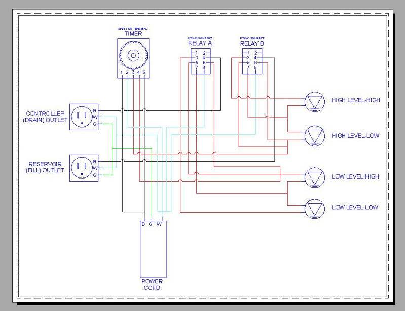
In the original build Orgre uses a - x1 SPDT FIVE Terminal Timer / Time Clock, 24Hr, 120V.

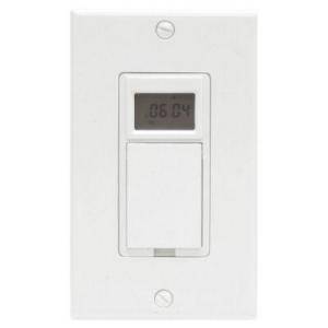
I will be switching this out for a GE 15 amp In-Wall Smart Digital Timer

Model # 15071

Internet # 100685868

Store SKU # 543476

Now in Orges DIY thread there is a member by the name of yamaha1fan he uses the digital timer and a third dpdt relay.

He states how to connect it but I don't get it.

YAMAHA1FANS writing
I finally got mine done. Had alot of other things to do as well. I went through hell trying to get that TA4079 timer, everybody was backordered. Then I started thinking, all I really needed was the double throw.

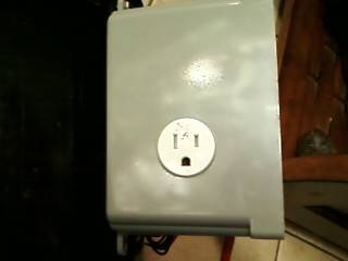
So I used a normal digital timer connected to a third relay. the relay is the same relay used for the switches. I couldnt find a SPDT at the local radio shack, so I just used one side, no biggie. I made a plug and wired #7 & 8 to the timer. That will control the relay. Everything that gets plugged to the relay side of the Diehl timer, gets wired to the third relay. I dont have it here, but one terminal is always hot, the other two get switched when the timer shuts on and off.


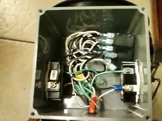
I have the 3 relays needed to get the job done just needs some help putting it together.
 

Hydropimp

Active member
Veteran
In yamaha1fan's post he talks about a plug that he made I don't want a plug just wire the timer to the relay.
 

Hydropimp

Active member
Veteran
I need heeeeeeeeeeeeeeeeeeeeeeeelllllllllllllllllllllllllllllllllllllpppppppppppppppppppppppppppppppppp


I have everything connected excepted the timer.

I have all the float wires hooked up and all the timer wires that needed to be hooked up to the SPDT FIVE Terminal Timer.

I took all the wires labeled timer in Orges thread and connected them to the 3rd relay. I need to know where do I connect the hot leg of the digital timer and the neutral?
 

Marshall

Member
the plug you don't want to make is required. It plugs into the outlet of the timer unless you have a timer with some type of lugs. That would go to 7 & 8.

It has been a while since I have done this but I did copy this and it worked fine.
 

Hydropimp

Active member
Veteran
marshall thanks for the reply

the timer i have it doesn't have plug ins its to be wired directly to the relay.

can you explain to me what the numbers on the back of the relay mean?
 

Marshall

Member
no because it has been so long since I have done this. All I remember is if you understand how relays work, and you understand how this original design works, it was easy to understand how the digital timer and 3rd relay works.

The plug would have been to plug to the timer. If you dont have an outlet on the timer, then you dont need a plug

At any given time one pump should be active. the digital timer, and the 3rd relay tell the other relays when to turn on and off.


Sorry man, it has been 2 or 3 years since I did this so I can not remember the details
 

Hydropimp

Active member
Veteran
It's cool bro you are the only one in here now some maybe we can get through this together.

I don't know how relays work or what the #s on the back of the relay mean.

I get this

At any given time one pump should be active. the digital timer, and the 3rd relay tell the other relays when to turn on and off.

But I don't know how to wire the timer to what number on the relay.

I wired everything as per the thread. even the wires that went to the mechanical timer I just wired it to the 3rd relay.

But what about the timer. If you have a chance look over orges thread and get back at me.

Thanks Marshall.

Take your time and use that brain because I can't seem to get this done.

I have it all done except the timer part.
 

Stay Puft

Member
Here is a drawing for you:
picture.php
 

MikeRo

New member
HOW TO CONVERT ANALOG EBB AND FLOW CONTROL FROM AN ANALOG TO A DIGITAL TIMER

HOW TO CONVERT ANALOG EBB AND FLOW CONTROL FROM AN ANALOG TO A DIGITAL TIMER

To convert from an analog timer to a digital you will need a third 110VAC relay and a digital timer. You can use the same DPDT Relay as the FILL and DRAIN relays. Look at the attached schematic for more information. WIRE COLORS ARE ONLY FOR READABILITY, EXCEPT GREEN IS GROUND, GREY IS COMMON, AND BLACK IS HOT.

DESCRIPTION OF PROCEDURE

Remove the wire attached to TERMINAL 1 of the analog timer. Reattach this wire to the BLACK wire from the digital timer.

Remove the wire attached to TERMINAL 2 of the analog timer. Reattach this wire to both the WHITE wire from the digital timer and TERMINAL 7 of the third relay (TIMER CONTROL – RELAY C).

Remove the wire attached to TERMINAL 3 of the analog timer. Reattach this wire to TERMINAL 3 of the third relay (TIMER CONTROL – RELAY C).

Remove the wire attached to TERMINAL 4 of the analog timer. Reattach this wire to TERMINAL 1 of the third relay (TIMER CONTROL – RELAY C).

Remove the wire attached to TERMINAL 5 of the analog timer. Reattach this wire to TERMINAL 5 of the third relay (TIMER CONTROL – RELAY C).

The digital timer will have a wire labeled LOAD that could be any color but is probably red or blue. Connect this wire to TERMINAL 8 of the third relay (TIMER CONTROL – RELAY C).

Attach the green wire from the digital timer to the green wire in the timer control box located at the receptacle.


P1100127.jpg

P1100128.jpg
 

MikeRo

New member
Digital Timer

Digital Timer

I decided to add a electrical box to the side of the box that I purchased from Aquahub. I like the Aquahub box because it is water tight and it is pre-cut for a receptacle. An option was to cut a rectangular hole in the center of the existing round hole and make a face plate to cover the outer edges. However, the digital timer would take up space and that was somewhat limited by the additional timer control relay. I would also have to install LED indicator lights to tell me when the pump or fill was active. I simply bolted the electrical box to the timer control box. I cut the screws even with the nuts, then I drilled a 1/2" hole in the side to run the wires through. Make sure to allow enough room for the strain relief connector.

picture.php
picture.php


For a list of where to get other parts see this.
 
Top