
-
Happy Birthday ICMag! Been 20 years since Gypsy Nirvana created the forum! We are celebrating with a 4/20 Giveaway and by launching a new Patreon tier called "420club". You can read more here.
-
Important notice: ICMag's T.O.U. has been updated. Please review it here. For your convenience, it is also available in the main forum menu, under 'Quick Links"!
You are using an out of date browser. It may not display this or other websites correctly.
You should upgrade or use an alternative browser.
You should upgrade or use an alternative browser.
2nd Build-DIY COB with Vero 29's x 6
- Thread starter Roasty McToasty
- Start date
")
 Nice build mang...
Roasty McToasty
Member
Thanks guys! Still have 1 more to build. I'll try and document the next one better for those interested. The string of 3 vero 29's metered 113v. 113 x 2.1 = 237.3w total. This thing is blindind lol.
Peace, Roast.
Peace, Roast.
Firebrand
Active member
The 237.3 watts being focused downward and spread to three points probably give light that is equivalent or better that a single 400 watt HID (HPS, MH, CMH), at almost twice the efficiency.The string of 3 vero 29's metered 113v. 113 x 2.1 = 237.3w total.
Roasty McToasty
Member
The 237.3 watts being focused downward and spread to three points probably give light that is equivalent or better that a single 400 watt HID (HPS, MH, CMH), at almost twice the efficiency.
Yes Firebrand, I will agree with that. The parts to build 2 of these costed about 460 dolla's, so 230 a piece. Not much more than a 400w hid setup. No bulb replacements, 1/2 the wattage, less heat, shoter profile for more height, more even coverage in my 5x5. Pretty much a no brainer. COB rigs FTW.

Peace, Roast.
Roasty McToasty
Member
Tutorial: Mechanical
Tutorial: Mechanical
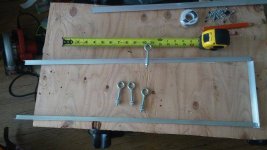
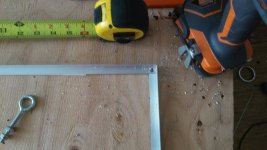
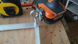
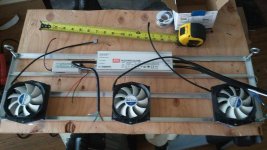
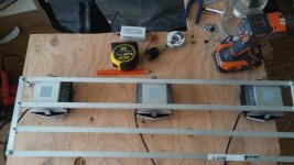
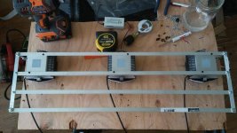
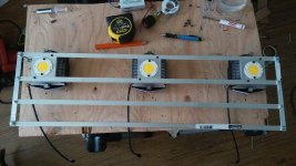
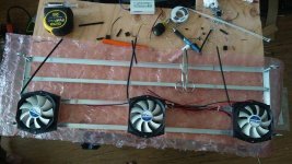
Ok, you will need 2, 8 foot sticks of 1/2 inch angle aluminum found at Home Depot. Cut 4 pieces at 28 inches (or smaller if you prefer) for the length of your rig. Then cut 2 pieces at 6 1/2 inches for width pieces. Take a long piece and a short piece and make a corner and drill a hole large enough for your eyelets to pass through. Use a nut on each side of the angle aluminum.


Repeat in all 4 corners.


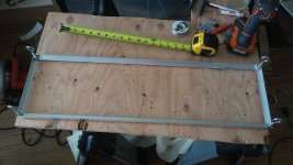
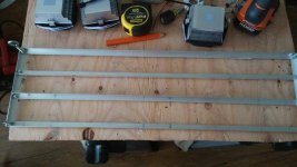
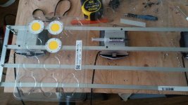
Place your Heat sinks and drivers in for dry fitting to get exact placement of middle rails.

Continued on next post.
Peace, Roast.
Tutorial: Mechanical
Ok, you will need 2, 8 foot sticks of 1/2 inch angle aluminum found at Home Depot. Cut 4 pieces at 28 inches (or smaller if you prefer) for the length of your rig. Then cut 2 pieces at 6 1/2 inches for width pieces. Take a long piece and a short piece and make a corner and drill a hole large enough for your eyelets to pass through. Use a nut on each side of the angle aluminum.
Repeat in all 4 corners.
Place your Heat sinks and drivers in for dry fitting to get exact placement of middle rails.
Continued on next post.
Peace, Roast.
Attachments
what do you think of these roasty ?
https://www.icmag.com/ic/showthread.php?t=318944
better than cree current flagship ? i don't think they release all the info on them until after the cann cup this weekend.
https://www.icmag.com/ic/showthread.php?t=318944
better than cree current flagship ? i don't think they release all the info on them until after the cann cup this weekend.
Roasty McToasty
Member
what do you think of these roasty ?
https://www.icmag.com/ic/showthread.php?t=318944
better than cree current flagship ? i don't think they release all the info on them until after the cann cup this weekend.
They look nice, I'm sure they'll kick ass, but the pricing will be a lot i think.
Peace, Roast.
Roasty McToasty
Member
Continued Mechanical
Continued Mechanical
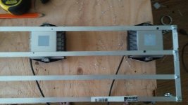
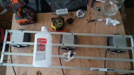
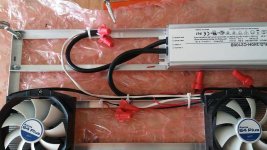
Drill your rails at the right spot. I use 3/16 drill bit and short 8-32 screw and nut.


Tighten everything down.

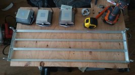
Position and mark your heatsinks.

Predrill 1/8" holes (for M3 screws) in the rails where the heatsink will sit. I recommend staying near the outside edge of the rail so that you have maximum edge of the sink.
CONTD....
Peace, Roast.
Continued Mechanical
Drill your rails at the right spot. I use 3/16 drill bit and short 8-32 screw and nut.
Tighten everything down.
Position and mark your heatsinks.
Predrill 1/8" holes (for M3 screws) in the rails where the heatsink will sit. I recommend staying near the outside edge of the rail so that you have maximum edge of the sink.
CONTD....
Peace, Roast.
Attachments
Roasty McToasty
Member
Continued Mechanical
Continued Mechanical
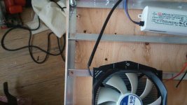
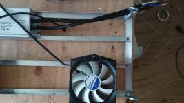
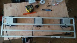
Flip over your frame and place each heatsink in their position. Make sure to face the fan wire to the center of frame. Use a 7/64" drill bit for all your heatsink drilling. The M3 screws will tap as you screw them in, if you use the 7/64" bit.


Wipe off shitty TIM that comes on the Arctic 64+.

Pull out one of your chips and place it where you like it on the sink. Mark your holes for each chip.

CONTD....
Peace, Roast.
Continued Mechanical
Flip over your frame and place each heatsink in their position. Make sure to face the fan wire to the center of frame. Use a 7/64" drill bit for all your heatsink drilling. The M3 screws will tap as you screw them in, if you use the 7/64" bit.
Wipe off shitty TIM that comes on the Arctic 64+.
Pull out one of your chips and place it where you like it on the sink. Mark your holes for each chip.
CONTD....
Peace, Roast.
Attachments
Roasty McToasty
Member
Continued Mechanical
Continued Mechanical
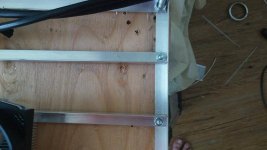
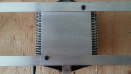
I'm only using 2 screws per chip.

Drill your marks with the 7/64" bit and drill deep enough for the M3 screw. I go all the way through to the fins.

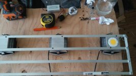
Clean off all the aluminum shavings around the sinks. Apply a very thin layer of some good TIM to your chips. I use Arctic 5 grease. See pic.
Be careful not to get grease all over the cob's emitting side.

Do one at a time, and be careful handling your chips. Secure all of them. Do not over tighten your screws. Watch carefully as you tighten and just snug them to the sink. Try to move them and if they stay put they are good, if they move tighten a little at a time till they stay put.

Attach your PICO EZ MATE connector to each COB making sure to match the positive and negative. I like to ty-wrap the cable to the frame for strain relief on the cable.

That's pretty much it for Mechanical. Next is Electrical.
Peace, Roast.
Continued Mechanical
I'm only using 2 screws per chip.
Drill your marks with the 7/64" bit and drill deep enough for the M3 screw. I go all the way through to the fins.
Clean off all the aluminum shavings around the sinks. Apply a very thin layer of some good TIM to your chips. I use Arctic 5 grease. See pic.
Be careful not to get grease all over the cob's emitting side.
Do one at a time, and be careful handling your chips. Secure all of them. Do not over tighten your screws. Watch carefully as you tighten and just snug them to the sink. Try to move them and if they stay put they are good, if they move tighten a little at a time till they stay put.
Attach your PICO EZ MATE connector to each COB making sure to match the positive and negative. I like to ty-wrap the cable to the frame for strain relief on the cable.
That's pretty much it for Mechanical. Next is Electrical.
Peace, Roast.
Attachments
Roasty McToasty
Member
Electrical
Electrical
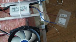
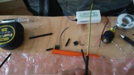
Next cut off the clips at the end of the fan wire. Carefully cut the wire wrap with scissors. Expose around 3-4 inches of wire. Cut off the blue and green wire as they are not needed. The yellow is your positive, and black negative. Strip each one with about 3/4" of exposed metal.

Bad pic of yellow/black wire from fans.

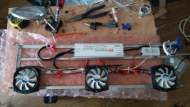
Place your drivers where you want them. Secure them if you want. I just ty-wrap the fan driver. And ty-wrap the input power cord of the cob driver.

Strip all of your Pico EZ mate wires for connecting. I also strip back a bit more off all the drivers cables as well. Makes connecting with wire nuts easier. Take your output red from your driver to the red wire of your first COB. Take your black wire from your 1st COB to red of second COB. Black from 2nd to red of 3rd. Black of 3rd to black of driver output. Easy right?
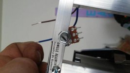
I drill a 5/16" hole in the frame where I want the pot to be. Mount pot to hole.


CONTD...
Peace, Roast.
Electrical
Next cut off the clips at the end of the fan wire. Carefully cut the wire wrap with scissors. Expose around 3-4 inches of wire. Cut off the blue and green wire as they are not needed. The yellow is your positive, and black negative. Strip each one with about 3/4" of exposed metal.
Bad pic of yellow/black wire from fans.
Place your drivers where you want them. Secure them if you want. I just ty-wrap the fan driver. And ty-wrap the input power cord of the cob driver.
Strip all of your Pico EZ mate wires for connecting. I also strip back a bit more off all the drivers cables as well. Makes connecting with wire nuts easier. Take your output red from your driver to the red wire of your first COB. Take your black wire from your 1st COB to red of second COB. Black from 2nd to red of 3rd. Black of 3rd to black of driver output. Easy right?
I drill a 5/16" hole in the frame where I want the pot to be. Mount pot to hole.
CONTD...
Peace, Roast.
Attachments
Roasty McToasty
Member
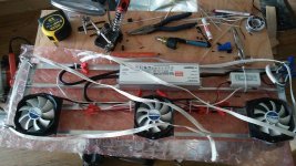
I run a 18/2 wire from my dim out to my pot. Then I solder the wire to the pot and wire nut other side to driver dim output.


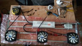
Then I wire all the fans in parallel to the fan driver. The farthest fan from the driver I had to add on a piece of 18/2 wire to reach the rest.
For the input power, use as long a piece of extension cord as you want, and cut off the female end. The drivers input will have a brown, blue, and green wire. Fan driver only brown and blue. So brown is a/c line in, blue is a/c neutral. Match brown from both drivers to black on extension cord. Match blue on drivers to white on extension cord. Match greens for ground.

Next I had some mule tape lying around so I made the hangers out of it. Simply run a piece through the eyelets on each side and tie a knot.

That's pretty much it. Cross your fingers and plug it in. Boom 1 badass rig. Secure the wires as you like.
Questions and suggestions are appreciated. 1000 ways to skin a cat.
Peace, Roast.
Then I wire all the fans in parallel to the fan driver. The farthest fan from the driver I had to add on a piece of 18/2 wire to reach the rest.
For the input power, use as long a piece of extension cord as you want, and cut off the female end. The drivers input will have a brown, blue, and green wire. Fan driver only brown and blue. So brown is a/c line in, blue is a/c neutral. Match brown from both drivers to black on extension cord. Match blue on drivers to white on extension cord. Match greens for ground.
Next I had some mule tape lying around so I made the hangers out of it. Simply run a piece through the eyelets on each side and tie a knot.
That's pretty much it. Cross your fingers and plug it in. Boom 1 badass rig. Secure the wires as you like.
Questions and suggestions are appreciated. 1000 ways to skin a cat.
Peace, Roast.
Attachments

Donkeybrains
Member
Nice rig brotha! Thanx for the detailed information. A lot of people will find this very useful.
Roasty McToasty
Member
Nice rig brotha! Thanx for the detailed information. A lot of people will find this very useful.
Thanks Donkeybrains!
Was hoping it would help peeps. It's not that hard with tools and know how. Paying it forward I suppose.
Peace, Roast.
Roasty McToasty
Member
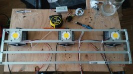
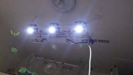
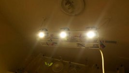
Hung this one in my veg room which is growing garden starts right now. Notice the color difference between dimmed and max.
Dimmed.

Maxed out.

Running at about 30% and its throwing some decent light.
Peace, Roast.
Dimmed.
Maxed out.
Running at about 30% and its throwing some decent light.
Peace, Roast.
Attachments
Been a busy bee I see... Looking Nice. And like that spread...
Roasty McToasty
Member
Been a busy bee I see... Looking Nice. And like that spread...
Thanks Twisted! Ya always something to do. Building rigs is fun so i don't mind. All done building for a while. Now i get ti look forward to a bunch of gardening. Indoor garden shuts down for summer so won't get to see results till late fall. Garden veggies are loving LEDs. As for spread i think I'm gonna like it.
Peace, Roast.
Wow that is a long time to wait... Have you done any par readings to compare to anything else like a MH or anything? No that Par is the end all be all with plant growth any way but I was just wondering.
Roasty McToasty
Member
Ya it sucks to wait, but i have a plethora of strains stashed for my head. Also promised the wife to shut down for a few months. Summer is least favorite season indoors. More problems to deal with. Plus I'm ready for a break. Been a slave to the girls too long. Sure I'll be longing for fall in no time lol. No meters but i think I'll have much better coverage and height.
Peace, Roast.
Peace, Roast.

