disfunktional
Member
awsum thanx man!! is there a thread that you could refer me to that uses this plc? or is the only one?
When using dpdt relays for flips, use only 1 relay for 1 ballast and switch the common and the hot. Some flip manufacturers use 1 relay for 2 ballasts/4lights, and this is dangerous.
HT
imnotcrazy,
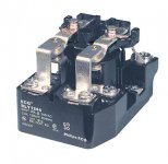
I am currently using White Rogers 94-389 type contactors in conjuction with C.A.P. Controls Nextgen 1000W ballasts without any problems since isolating each ballast to it's own individual contactor.
Contactor Specs: http://www.white-rodgers.com/wrdhom/pdfs/06_Cat_pages/Cat_06_pg0108.pdf
This is the correct relay to use for a flip, rated for 600V constant voltage, and will handle the 5000V to 6000V ignitor surge.
So one contactor 2 poles, except they don't have the capability of breaking the common to the bulb. Are you using them to power the ballast or to switch from one hood to another??
I am talking about switching to a 2nd hood every 12 hours: 2 rooms 12/12 1 ballast run 24/7
Again, I do not know if my setup would have an issue with a higher quality digital ballast. These were the Galaxy/HTG/MD Hydro/Digital Greenhouse 600W
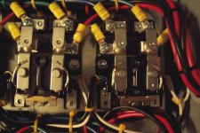
Not sure what could be causing your digital ballasts to fail, they may be bad batch. I noticed that you didn't use terminal lugs to connect the wires to the screw terminals. Since it's stranded wire, as you tighten the screws, the pressure crushes the strands, this could be a problem. Best bet is to get a ratchet crimper and use insulated terminal lugs, the "round" ones. Nice box though, PLCs are great.
muttley
")


Carter,
Could you please provide us with more detailed information with regards to the components necessary for the "el cheapo temperature sensor" I am very interested.


Also, thank you for sharing those photos of your work, it is a great example of what standards most of us in the community should demand, or in the case of DIY projects, standards that we should be striving to achieve.