What's new

Grow controller? (DIY)

qbert

Member
Ok... Time for you guys to chime in... I'm going to start layout & testing of a shield setup specifically designed for this type of use... Trying to figure out if I'm missing anything - or not realizing if there's other things people need...

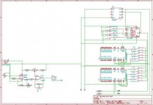
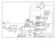
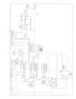
Right now; shield is going to contain:
Real time clock (DS1307 - I2C connected) - Gives us accurate date/time keeping.
Port Expander (PCF8575 - I2C connected) - To provide ports for LCD & Keypad
I2C Connected LCD controller - so you can plug a HD44780 LCD straight in
Ports for the Keypad (Just plug it in)
pH OP Amp circuit - with BNC connector (just plug in your probe)

Should leave us 12 Digital I/O pins; and 5 Analog I/O. Which I'm thinking get setup with something along the lines of headphone jacks for ease of connection (though GM Weatherpack connectors are tempting)

Think this is adequate or should I add another 16 channel i2c port expander. Running off a few ballparks I've seen - and parts costing based on retail - we're only talking ~75$ so far assembled, tested and shipped (based on an order of 30 units).


That sounds like quite a bit for $75. I'm surprised.

I'd love to look into this more and give ya my opinion, but I'm knee deep starting a cab build like now, so there's no time.
 

Hephaestus

Member
That sounds like quite a bit for $75. I'm surprised.

I'd love to look into this more and give ya my opinion, but I'm knee deep starting a cab build like now, so there's no time.

Yes and no... You're still going to have to supply your own arduino decimilia/freeduino (30$+/-); power center (40$ up to ridiculous); LCD (~10$ on ebay); 4x4 keypad (~10$ ebay again), all your sensors - which could add up quickly (25$ pH; 2$ each for the DS18B20s)... Then a place to put it all together; and probably a wall-wart or two (pH circuit needs a >6v power source... To make it run on 5v runs the price up from ~3$ closer to 15$ - might just put a 9v battery into the circuit like I've done on my other systems).
 

LEDGro

Member
Wow thanks alot for this. Im only on page one and the instructables link will be invaluable info to add to my LED build!
 

Hephaestus

Member
Well last night was productive... Killed off at least 2 trees - why is it impossible to read a datasheet on a screen? :joint:

My initial layout of the shield got tossed... Yes SMT parts are cheap like borscht, and take up little space; but good old DIP sized IC circuits can be built by :rasta: 's with a soldering iron like you and me...

So I'm reworking with some easier to handle components... Basically - I'm hoping by the weekend I'll have a schematic & PCB design you can build along at home for those itching to give it a whirl...

That is if I get off my ass; roll a gagger :kos: for some patience and figure this eagle cad program out...
 
M

medi-useA

I'll still be here, scratchin me noggin and thinking.:)

That's the prob with diving into a field I have no exp. in.... But I think with research it will be possible to build a grow controller unit with off the shelf parts and 20 hrs work....

@least so I'm hoping......

muA
 

Hephaestus

Member
Well around midnight gave up on eagle - went over to kicad - much easier :) Should have the schematic up tomorrow...

Don't think you'll be quite off the shelf just yet... But once we get past xmas - I'll get some PCB's ordered, pre-assembled for not too much... You'll still have to put together the details of the unit (what you're controlling, sensor arrays etc) thus I don't see ever being 100% off the shelf (ie go to walmart buy a sensor kit, plug it in and go...) but if you can solder, and follow some of the others who'll probably build along; won't be so bad...

It's this major hardware setup that's the headache, I figure if a shield exists so you don't have to sit down with 12 different datasheets and figure out what wire goes to which pin - that eliminates half the headache right there... Plug in your LCD, keypad, pH probe, sensors & power center, do a quick configuration of your program, and upload it... That's something not beyond the average person...

Did go with 2 MCP23016P port expanders in the design (What the heck, its a 2$ chip!) That'll leave ~20 free digital ports on the shield + the remainder on the arduino (really I'm only using the SDA/SCL ports on the analog side; and one other analog port).
 

Hephaestus

Member
:joint:

if you're wondering what's taking so long ...

Lower left is the ph circuit; right is the 2 port expanders, real time clock, and eeprom; gotta rework some of it (was going to put switches on for setting addresses - but decided it's better to just hardwire those)

Yup still gotta add the lcd circuit, keypad circuit and figure a reasonable way to get all these components into a plug n play type scenario...
 

Attachments

  • growshield.jpg
    growshield.jpg
    31.4 KB · Views: 16

Hephaestus

Member
Keeping the high voltage and low voltage as separate as possible...

The picture I have in my brain... Is to use a power center - like has been done in other places:
Take your pick - this is the american dj100a hack:
Controller_mock_b.jpg

Or something a little simpler like you'll find on this page:
http://reefprojects.com/w/phpBB3/viewtopic.php?f=8&t=21

Basically an arduino digital output goes to a solid state relay (or regular 5vdc -> 110v - not as reliable but cheap) that digital output turns on the 110v circuit... whatever you've got plugged in turns on/off...

Keeping high and low voltages separate is a good thing :)
 

Hephaestus

Member
Ok, can you guys read this attachment? :joint: It was enough fun to export it into a picture so it could be uploaded...

No 100% guarantees - but it should work (the 4k7 pullup resistors on scl/sda should be unneeded but I figured as there was some argument - I'd allow for them...) Feel free to build/test - chips are the DS1307 24LC256 MCP23016 (x2) and a tl062.
 

Attachments

  • growshield.jpg
    growshield.jpg
    49.9 KB · Views: 16

Hephaestus

Member
ok... So answered my own question on this one... Can't see a darn thing...

Ok so where can I host a huge jpg image without it getting resized/edited to nothing?
 

Attachments

  • Printing Preview.jpg
    Printing Preview.jpg
    33.8 KB · Views: 14
Keeping the high voltage and low voltage as separate as possible...

The picture I have in my brain... Is to use a power center - like has been done in other places:
Take your pick - this is the american dj100a hack:
Controller_mock_b.jpg

Or something a little simpler like you'll find on this page:
http://reefprojects.com/w/phpBB3/viewtopic.php?f=8&t=21

Basically an arduino digital output goes to a solid state relay (or regular 5vdc -> 110v - not as reliable but cheap) that digital output turns on the 110v circuit... whatever you've got plugged in turns on/off...

Keeping high and low voltages separate is a good thing :)

ok i understand now. a relay for each 120v ac to be used. i knew that outlet strip with the on/off switches looked familiar, i was looking at those to mount in the freezer of my minifridge. thanx again for yet another lesson!!
 

Hephaestus

Member
Yup - those american DJ100A switches are awesome - especially in this application... Having an override (ie the switch) to kill power if needed + lights (lit switch) to show when it's actually powered by the controller = perfect. But it's cheaper to build one - but the nice housing is hard to beat.

I'm still thinking using RJ45 to make it plug n play - only problem is 8 data lines total; would have to use the shielding as a ground for the unit; not the greatest solution but it'd work...And I'm pretty sure everyone has some ethernet cable lying around - or easily accessible...
 
lol i have no idea what you just said. i know what the shielind is that you're talking about, but the RJ45 and 8 data lines lost me, and iv heard ethernet alot but i dont know what that is either. i know i know im way behind the times, but im trying to catch up.
 

Hephaestus

Member
Haha... Ok look at your computer - probably has a plug in for internet access (likely says ethernet 10/100 or something similar on it - looks like a bigger phone jack). My thinking is using that style plug/cable is easier than something completely custom - to connect the shield to another device (in this case the power pack - as pictured above).
 

Hephaestus

Member
The little ones send the signal, there's a ground + signal (digital); when the signal is high (5vdc) the 110v circuit is closed...
 
hey bro iv worked up a list of everything i that i think i would like to control or monitor. here we go.

control:1-150w hps light (digital ballast)
1-pc fan (for blowing on the light)
1-Exhaust fan
1-Air pump
1-Water pump (for emptying the res out, however in the future will be used for aeroponic set up)

monitor 1-Nute temp with high/low temp alarm
1-Nute pH with pH high/low alarm
1-Nute EC with EC high/low alarm
1-Nute level with level low alarm
1-Intake air temp
1-Canopy air temp
1-Utility air temp
1-Wind sensor (if it measures cfm)

as far as the alarms i dont need an audible one maybe something on the lcd screen, flashing temp reading, or "temp high" read out, or maybe a combo of both. dont want it to be audible for stealth reasons.

well theres the list im sure that there maybe more to be added but thats all that i could think of for now.
 

Latest posts

Latest posts

Top