plutosmoke
Member
make a GitHub repository so others can see and give inputs
make a GitHub repository so others can see and give inputs
I have yet to see a VPD controller on the market under like $1k - they are usually for greenhouses. I have a Pi and watching closely.
It's the coding part that is going to take the most skill. So hopefully some smart coder comes along here.
EDIT: I have just put up a bounty on a freelancer website - willing to throw some decent money on just the software. If anyone knows a good coder please PM me.
how hard is it to set up a rasberry pi to use your code Can Of Bliss? I don't have programming skills but am pretty good with computers. I have experience with installing openElec and Rasbpian and RetroPie on Rasberry Pi's. I know how to build PCs. Would setting up my own automated controller be really difficult?
what is the code you wrote intended for? Arduino? I was hoping that setting up a computerized automated controller woulld be as simple as maybe copying and pasting someone elses code and flashing/installing it to a specific device like the arduino or rasberry pi where it would just run the code upon startup. Is that not how these arduinos work?I use a Pi as my primary computer right now, but I don't know much about how to use it.
I believe there is a way to run a C program on a Pi, but most people use python. I know next to nothing about python, but it is probably possible to convert a simple program like this. It's on my list of things to do, but no promises.
A "library" needs to be loaded so that it knows what to do with the sensor. I'm not sure how that works on the pi, so that's another step that needs to be figured out.
As to the possibility of setting up an automated controller. I would suggest you learn to write some code, you don't need to get good at it. Being able to understand a program is more important than being able to write from scratch.
Something to consider is the reliability of the controller and its failure mode. It's always wise to add backups.
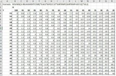
float vpd = round((1-hum/100)*0.611*exp(17.27*cel/(cel+237.3))*10*10)/10.0;
passing in floats of "cel" = temp C and "hum" = humidity, this will return the vpd. This works as expected with an arduino or photon and returns numbers as shown in the chart given a specific temp/humidity.

Awesome! Good stuff.
One note, I noticed you're not using the round() function on the formula which is fine BTW. But if not using round, you can simplify the formula using it like this:
=(1-hum/100)*0.611*exp(17.27*cel/(cel+237.3))*10;
this will give an exact number like 13.78
to round the number to 13.8, I used some math gymnastics to force the decimal rounding which adds the extra parts to the formula.
round((1-h/100)*0.611*exp(17.27*t/(t+237.3))*10*10)/10.0;
The bold parts are not necessary if not using rounding.
Maybe for clarity, it should be:
vpd = (1-h/100)*0.611*exp(17.27*t/(t+237.3))*10; //actual formula
vpd = (vpd*10)/10.0; //math gymnastics to round vpd value to 1 decimal,if needed
I'm also going to change my auto-humidification code to use VPD as well. Right now I just pop it on if < 40% and turn off at 50% regardless of temp. Great thread!
can you guys tell me what i need to google and learn in order for me to apply the code?
can you guys tell me what i need to google and learn in order for me to apply the code?