A dewd named Poiseuille figured out how air flows and published a formula that is used today to figure out the numbers for designing a proper air flow system.
The basis of "Poiseuille's Law" states that air will flow from an area of high pressure to an area of lower pressure.
We see examples of this all the time, although we probably aren't thinking much about the physics behind these events.
One of the most obvious examples of this law is the vacuum cleaner. When the vacuum is running, it has a fan that is sucking the air out of a canister which lowers the pressure inside the canister. The pressure on the outside of the vacuum hose is greater than that inside of the canister, so air flows from an area of high pressure (the atmosphere) to an area of lower pressure (inside the vacuum canister).
Now, put your hand slightly over the nozzle end and you can immediately feel that you have blocked some of the air flow into the nozzle. This does two things...first it lessens the amount of air that can come into the nozzle end. By having less air volume coming it the hose, the pressure inside the canister increases. You can easily hear the vacuum motor increase in noise, as it is trying to overcome the blockage of air flow that you have created with your hand. The only way to stop the vacuum motor from laboring is to take your hand away and allow the air volume to increase, which allows the flow to return to normal.
This is exactly what is happening inside our grow boxes. They are essentially vacuum canisters.
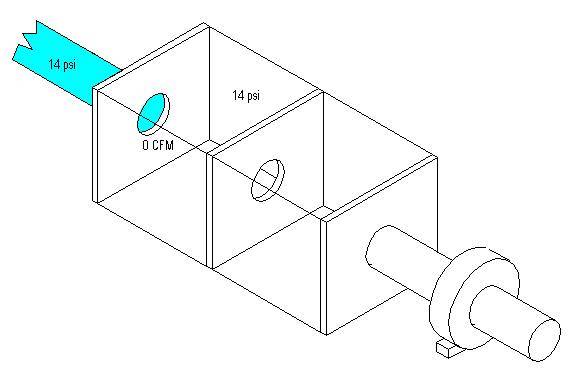
We know from Poiseuille's Law that air will not travel through an orifice if the pressure is the same on both sides of the hole.
Here we have a box with an incoming pipe of air. There is equal pressure in both the pipe and the box, so the air will just sit there and not move.
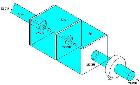
Once we turn on our fan, the pressure inside the box starts to drop. This immediately causes the air in the pipe to rush into the lower pressured box's first chamber, at the same time all the air in the first chamber is flowing out of the first chamber and into the second...
Let's assume the pressure in the pipe is 14 psi, and when the fan is turned on the pressure in the box is lowered to 10 psi. This means the air is entering into the box with 4 pounds per square inch (psi) of force, which makes it easy to see how air will flow into an area of lower pressure.
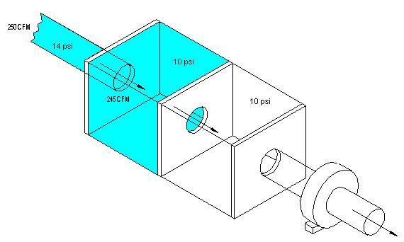
The air is now filling the first chamber and flowing through to the next chamber.
Now, there are some other things happening with this flow that we do not see. For one, every time the air mass passes through an orifice (or hole) it sees some turbulence and friction that causes little fluctuations in pressure.
What happens in the end is that the air flow that was traveling at 250 CFM sees a slight bit of resistance at the hole and now travels at 245 CFM.
It looses a little bit of CFM with every hole it passes through...
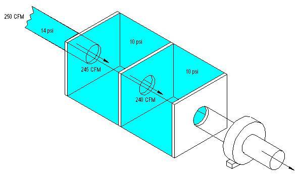
If there were no resistance caused by the holes, and if we had a fan that could pull 250 CFM through a 6" pipe, then our air would pass cleanly through all the holes until it reached the fan and exited at 250 CFM. But the fact is that we do see some loss at each hole.
With the exact same size entry holes as the exit hole, we lose some CFM.
There are two ways to get the full 250 CFM at the exit.
One way would be to increase the speed of the fan to a higher CFM rating. In my example we lost 15 CFM from start to finish, so if I started with a fan that could pull 265 CFM, then I could essentially end up with my 250 CFM using the holes as they are.
The problem is that most fans are running at peak to begin with. So you can usually not increase them.
The alternative to get the 250 CFM we want is to open up the intake holes. By making the holes bigger, you will be adding the needed air flow that the holes inside the box are going to rob you of.
HVAC men know that they need a minimum of 10% larger opening than exit, because they understand the physics that we are discussing here.
We often get the recommendation to open up our intakes twice the size of the opening, but that is normally overkill. All you need to have is enough air flowing in to satisfy the fan and it's CFM rating. The mass flowing out is equal to the mass flowing in.
Although you can never really have your intake too large, you can easily have it too small.
Orifice Area
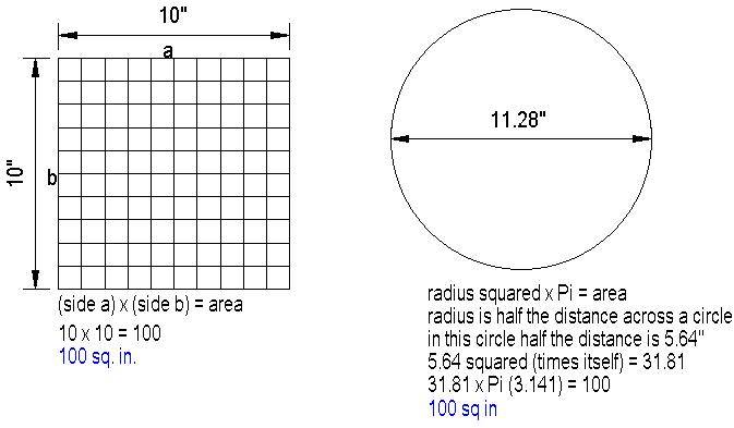
To properly size our air flow holes, we need to know how to figure the area of each shape. Both a 10" x 10" square and a 11.28" diameter circle have a surface area of 100 square inches.
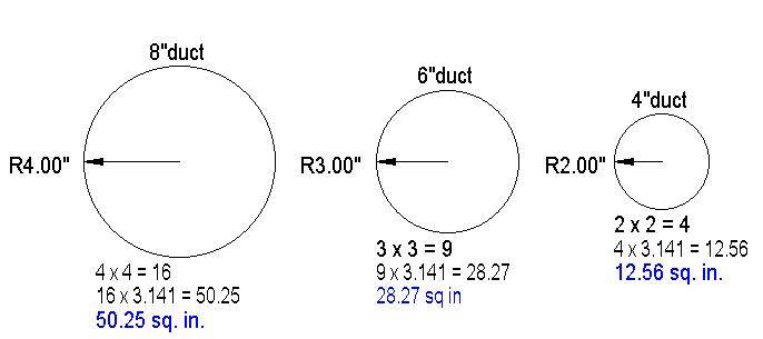
Here are some examples of duct and pipe sizes and the area figures for them:
Let's assume I have a 6" ducted fan.
We know that a 6" duct hole has a surface area of 28.27 sq. in.
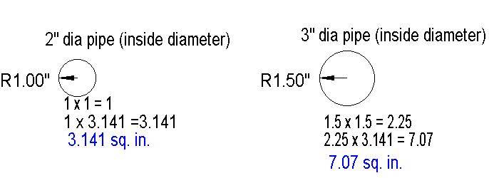
I decide that I want to use 3" pvc pipe for my light blocking intake holes.
We know that a 3" pipe hole has a surface area of 7.07 sq. in.
28.27 divided by 7.07 = 3.999 So I need 4 3" pipes to equal the 6" exhaust opening. But, I want at least 10% more opening to account for my losses through the holes, so I will add another 3" pipe, which is more than 10% over sized, and should do the job.
Knowledge will forever govern ignorance; and a people who mean to be their own governors must arm themselves with the power which knowledge gives.
-James Madison
The basis of "Poiseuille's Law" states that air will flow from an area of high pressure to an area of lower pressure.
We see examples of this all the time, although we probably aren't thinking much about the physics behind these events.
One of the most obvious examples of this law is the vacuum cleaner. When the vacuum is running, it has a fan that is sucking the air out of a canister which lowers the pressure inside the canister. The pressure on the outside of the vacuum hose is greater than that inside of the canister, so air flows from an area of high pressure (the atmosphere) to an area of lower pressure (inside the vacuum canister).
Now, put your hand slightly over the nozzle end and you can immediately feel that you have blocked some of the air flow into the nozzle. This does two things...first it lessens the amount of air that can come into the nozzle end. By having less air volume coming it the hose, the pressure inside the canister increases. You can easily hear the vacuum motor increase in noise, as it is trying to overcome the blockage of air flow that you have created with your hand. The only way to stop the vacuum motor from laboring is to take your hand away and allow the air volume to increase, which allows the flow to return to normal.
This is exactly what is happening inside our grow boxes. They are essentially vacuum canisters.
We know from Poiseuille's Law that air will not travel through an orifice if the pressure is the same on both sides of the hole.
Here we have a box with an incoming pipe of air. There is equal pressure in both the pipe and the box, so the air will just sit there and not move.
Once we turn on our fan, the pressure inside the box starts to drop. This immediately causes the air in the pipe to rush into the lower pressured box's first chamber, at the same time all the air in the first chamber is flowing out of the first chamber and into the second...
Let's assume the pressure in the pipe is 14 psi, and when the fan is turned on the pressure in the box is lowered to 10 psi. This means the air is entering into the box with 4 pounds per square inch (psi) of force, which makes it easy to see how air will flow into an area of lower pressure.
The air is now filling the first chamber and flowing through to the next chamber.
Now, there are some other things happening with this flow that we do not see. For one, every time the air mass passes through an orifice (or hole) it sees some turbulence and friction that causes little fluctuations in pressure.
What happens in the end is that the air flow that was traveling at 250 CFM sees a slight bit of resistance at the hole and now travels at 245 CFM.
It looses a little bit of CFM with every hole it passes through...
If there were no resistance caused by the holes, and if we had a fan that could pull 250 CFM through a 6" pipe, then our air would pass cleanly through all the holes until it reached the fan and exited at 250 CFM. But the fact is that we do see some loss at each hole.
With the exact same size entry holes as the exit hole, we lose some CFM.
There are two ways to get the full 250 CFM at the exit.
One way would be to increase the speed of the fan to a higher CFM rating. In my example we lost 15 CFM from start to finish, so if I started with a fan that could pull 265 CFM, then I could essentially end up with my 250 CFM using the holes as they are.
The problem is that most fans are running at peak to begin with. So you can usually not increase them.
The alternative to get the 250 CFM we want is to open up the intake holes. By making the holes bigger, you will be adding the needed air flow that the holes inside the box are going to rob you of.
HVAC men know that they need a minimum of 10% larger opening than exit, because they understand the physics that we are discussing here.
We often get the recommendation to open up our intakes twice the size of the opening, but that is normally overkill. All you need to have is enough air flowing in to satisfy the fan and it's CFM rating. The mass flowing out is equal to the mass flowing in.
Although you can never really have your intake too large, you can easily have it too small.
Orifice Area
To properly size our air flow holes, we need to know how to figure the area of each shape. Both a 10" x 10" square and a 11.28" diameter circle have a surface area of 100 square inches.
Here are some examples of duct and pipe sizes and the area figures for them:
Let's assume I have a 6" ducted fan.
We know that a 6" duct hole has a surface area of 28.27 sq. in.
I decide that I want to use 3" pvc pipe for my light blocking intake holes.
We know that a 3" pipe hole has a surface area of 7.07 sq. in.
28.27 divided by 7.07 = 3.999 So I need 4 3" pipes to equal the 6" exhaust opening. But, I want at least 10% more opening to account for my losses through the holes, so I will add another 3" pipe, which is more than 10% over sized, and should do the job.
Knowledge will forever govern ignorance; and a people who mean to be their own governors must arm themselves with the power which knowledge gives.
-James Madison
")