What's new
  • Happy Birthday ICMag! Been 20 years since Gypsy Nirvana created the forum! We are celebrating with a 4/20 Giveaway and by launching a new Patreon tier called "420club". You can read more here.
  • Important notice: ICMag's T.O.U. has been updated. Please review it here. For your convenience, it is also available in the main forum menu, under 'Quick Links"!

BASIC PRINCIPLES OF GOOD WIRING (fyi)

I.M. Boggled

Certified Bloomin' Idiot
Veteran
DANGER!:please be wide awake and aware of the inherent dangers of electricity before starting to "play around" with it as it is mean and unforgiving and will viciously bite, perhaps even kill if not respected. IMB :)
>>>>>>>>>>>>>>>>>>>>>>>>>>>>>>>>>>>>>>>>>

Electricity can be an intimidating concept for many because of the potential danger.
You can virtually eliminate that danger with a little knowledge and proper safety practices.
However, regardless of how much knowledge you have, never become lax in dealing with an electrical system, or it can be deadly.


* Before beginning any electrical repair, shut off the power. Remove the fuse or trip the breaker for the circuit you will be working on in your service panel. Use a neon tester to be sure the power is off. If there is any doubt, you can remove the main fuse or trip the main breaker. Remember: Removing the main fuse or tripping the main breaker will usually shut off the power to the entire house.


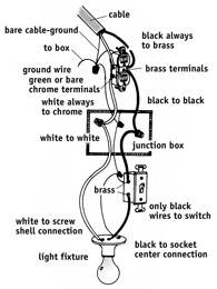
* Electrical wires are color coded to prevent wiring errors.

* White wires almost always connect to other white wires or to chrome terminal screws on switches and receptacles.

* Some wiring devices–such as receptacles–are back-wired by pushing the bare wire end into spring grip holes. These wiring devices are plainly labeled to show which color goes into each spring grip hole.

* Switches are nearly always connected into black wires in cables. The only exception is where a cable is extended, making it necessary for the white wire to play the role of the black wire. When this is necessary, the white wires should be painted black to prevent future wiring errors.

* Study the wiring diagram.
This will help you understand the basic principles of good wiring.
Also, find a good electrical how-to book.
It's one book every homeowner should keep on hand for ready reference.

* Most home wiring is complete with either No. 14 gauge or No. 12 gauge wiring. No. 14 is the smallest wiring permitted under most codes.

* Always use the same size cable for a continuation of any extended wiring circuit.


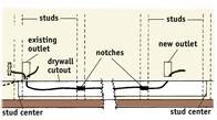
CONNECT NEW WIRING TO LAST OUTLET IN CABLE

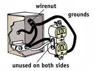
* New wiring should be connected to the last outlet in a run of cable. To locate the last outlet in the run, shut off the current. Remove the cover plates from each outlet on the circuit. The last outlet in the run has wires connected to only two of the four terminal screws.

* The two unused terminal screws on the last receptacle serve as a starting point for wiring to a new outlet.


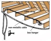
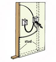
ATTACHING CABLE FOR NEW WIRING

* Shut off the power to the circuit you will be working on at the service panel.

* Loosen the screws holding the receptacle in the box and remove it.

* Attach the white wire to the chrome terminal, the black wire to the brass terminal on the receptacle and to the box, if the box is metal.

* Use care to match the size of the original cable. If No. 12 wire is used, continue with No. 12. If No. 14 wire is used, use No. 14 for continuing the cable. The size of the cable is usually stamped on the side of the cable.

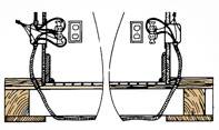
* New wiring can be connected to continue the run beyond the last receptacle . Note that the new wires are pulled through knockout plugs in the back of the outlet box.


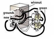
ADDING NEW WIRING FROM A JUNCTION BOX

* New wiring can also be tied into a junction box, unless the wiring in the junction box is already at maximum capacity.

* Before tying in at a junction box, always trace the cables leading to the box to check the voltage. Be sure you are not connecting a 120-volt outlet to a run of wire providing 240 volts for larger appliances.

* To tie in new wiring at a junction box, first shut off the current at the service panel.

* Locate the main supply cable coming into the junction box from the service panel. Locate the supply wire by tracing the white wires. All white wires in the junction box will be attached to the white wire on the supply line

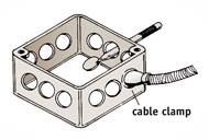
* Knock out the unused plug on the junction box and run the new line from the box as illustrated.
Be sure to use a cable clamp to secure the cable to the junction box.

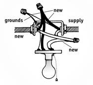
TYING IN NEW WIRING AT A CEILING LIGHT

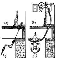
* You can tie in new wiring at a ceiling light if the light is not controlled by a switch.

* Shut off the current at the service panel.

* Tie white wires to white wires and black wires to black wires..

* Connect the ground wires as illustrated. If you are using a metal box, attach them to the box as well as the light fixture.

* Knock out an opening in the outlet box, and continue the new wiring as illustrated.
 
Last edited:

I.M. Boggled

Certified Bloomin' Idiot
Veteran
ALWAYS MATCH CONNECTORS TO TYPE OF CABLE USED

ALWAYS MATCH CONNECTORS TO TYPE OF CABLE USED

* Some boxes come with built-in connectors.

* Armored cable connectors have inner rims to hold fiber bushings at the end of the cable.

* Nonmetallic cable connectors are designed to grip the installation around the cable with a two-screw clamp.

* Regardless of the type of cable used, always leave about 6" to 8" of wiring in the box to allow plenty of wire for making easy connections.

* You can tighten the nut on either type of cable connector by placing a screwdriver in the notch and tapping the screwdriver lightly.


MAKE ALL CONNECTIONS IN APPROVED BOXES

* Always remember that connections must be made in an approved box. Never connect one cable to another by an open-line splice.

* All switch, outlet, and junction boxes must be positioned so they are always accessible.

* You can easily remove knockout plugs with a nail punch, screwdriver or metal rod.


RUNNING NEW CABLE BETWEEN MULTIPLE FLOORS

* Drill a hole through the floor from bottom to top. Be sure the hole is drilled into the recessed area behind the wall rather than in the open. Be sure to use a bit that's large enough to permit free passage of the wiring cable.

* Run the cable through the newly drilled hole to the desired location for the new receptacle or switch .

* Bring the cable through the opening by using a weight on the end of a string and a wire with a hook on the end .

* Using this same technique, you can add one outlet to another by drilling up through the floor, pulling the cable under the floor, and then running it to the desired position on the opposite wall . The same wiring can be pulled through for either receptacles or switches.


ADDING NEW WIRING FROM BOXES IN CEILING

* If your home has an unfinished attic, it may be easier to add new wiring by attaching it to boxes in the ceiling. In this way, gravity works for you rather than against you.

* Attach the cable to the box as previously described.

* Cut a hole in the wall at the desired location for the switch or receptacle, and run the cable from the box in the ceiling to the new outlet location.

* Bring the new cable through the wall and ceiling by cutting and drilling holes in and through the wall, the 2x4 plate, and the ceiling. A special fish tape is available for these types of jobs.


ADDING NEW WIRING ON THE SAME WALL

* You can connect new cable from an existing outlet to a new outlet on the same wall by running it inside the wall. Mark the approximate location of the new outlet. Using a stud finder locate and mark the wall studs. Start one stud before the existing outlet and end one stud after the new outlet.

* Mark the exact location of the new box. Make it the same height as the existing box. Do not locate it over a stud. Using a drywall or keyhole saw, cut the opening for the new box.

* Using a utility knife and a drywall saw, cut a strip of drywall about 3" wide out of the wall, below the outlets. Start at the center of the first stud you marked and end at the center of the last stud; watch for nails as you cut. Carefully remove the drywall strip.

* Using a hand or circular saw, make two cuts 1" apart and 3/4" deep in each of the exposed studs. Using a hammer and a chisel, remove the wood between the two saw cuts.

* Be sure the power is off to the existing outlet.
Remove the cover plate and the receptacle. Remove one of the knockouts in the bottom of the box. Run the new wire behind the wall and up through the knockout in the box. Tighten the clamp and attach the wires. If the box does not have a clamp, place a wire clamp on the new cable. Tighten the screw to hold the clamp on the wire. Be sure the nut is off the wire clamp and run the wire up to the box as before. Feed the threaded end of the clamp up through the knockout, replace the nut and tighten. Replace the receptacle and the cover plate.

* On the new box, remove one of the knockouts in the bottom of the box. If the box you are using is a self-clamping box, insert the box into the wall and tighten. If not, insert the box into the wall, insert a Madison hanger on each side of the box, and bend the tabs over into the box to tighten.

* Finish running the wire from the existing box through the notches and up behind the wall into the box as before. Clamp the wire and install the receptacle as in Fig. 3. Install the cover plate, turn on the power, and test the circuit with a neon tester. Shut off the power again to safely finish the project.

* Nail metal cable protectors to the exposed studs over the notches. Replace the drywall strip you removed earlier. Use the spackling compound and drywall tape to complete the installation.

* Cable can be pulled from an existing box on one wall to a new outlet on the opposite side of the same wall.

* Attach a cable to the existing receptacle in the box as previously described. Allow ample slack in the cable to permit easy connection to the new box to be installed on the opposite wall.

* Bring the cable through the new opening with a wire.

* Connect the cable to the new box, attach the desired receptacle, and mount the box to the wall with box supports if it is not near a stud.

http://doityourself.com/electric/index.shtml
 
Last edited:

I.M. Boggled

Certified Bloomin' Idiot
Veteran
Ground-Fault Circuit Interrupters

A Ground Fault Circuit Interrupter (GFCI) detects any loss (leakage) of electrical current in a circuit that might be flowing through a person using an electrical product.
When such a loss is detected, the GFCI turns electricity off before severe injuries or electrocution can occur. (However, you may receive a painful shock during the time that it takes for the GFCI to cut off the electricity.)

GFCI wall outlets can be installed in place of standard outlets to protect against electrocution for just that outlet, or a series of outlets in the same branch.

A GFCI Circuit Breaker can be installed on some circuit breaker electrical panels to protect against electrocution, excessive leakage current and overcurrent for an entire branch circuit.

Plug-in GFCIs can be plugged into wall outlets where appliances will be used.


Electrocution prevention w/ GFCI's
http://www.icmag.com/ic/showthread.php?t=4315

Electrical Safety For Indoor Growrooms
http://www.icmag.com/ic/showthread.php?t=15468

:cool:
 
Last edited:
G

Guest

Good Info IMBoggled.
Wiring is intimidating but VERY easy to learn it you respect it.

It should be doubly stressed that all connections HAVE TO BE MADE INSIDE ELECTRICAL BOXES! !

No wire nuts a dangling :moon:
 
G

Guest

indeed, thanks for all of the great pictures. visual refferance can be very reassuring when it comes to electrical.

-ms
 

guineapig

Active member
Veteran
on a related note once, when i was young and foolish, i bought an ionizer and put it in a small closet which was lined with mylar.....everything was fine until the mylar developed wrinkles and i was suprised when little blue sparks began to jump around the creases in the mylar! so i suppose remember- if you are working with mylar it can still conduct electricity albeit a very small amount. just remembered that story! -gp
 
G

Guest

Here is a quick guide below for residential wiring sizes and breakers in the United States most growers are likely to encounter.

Dudes are sometimes wondering what size wire should go with what size breaker. Don't ever skimp in this area as this is probably the biggest reason fires occur for growers.

* Note: When working with electrical wiring, bigger is always better as a rule of thumb for wire sizing. If you are exceeding ~ 100 feet in length in electrical run, make sure you "upsize" your wiring one size to compensate for line loss due to the length of wiring.

Here is a quick chart for COPPER WIRE ONLY:

14 AWG = 15 Amp Breaker
12 AWG = 20 Amp Breaker
10 AWG = 30 Amp breaker
8 AWG = 40 Amp breaker

* Note: Do not exceed 80% of a breakers capacity for safety. For instance, a 20 amp breaker should have no more than 16 amps on that circuit. (80% x 20 amps = 16 amps.

*15 amp breaker x 80% = 12 amp max load.

Add up all the amps of all your appliances on any given circuit to make sure you are indeed "safe" and stay at 80% or under of the breakers capacity.
 
Last edited:

UV Dreams

Member
ThunderBolts said:
Here is a quick chart for COPPER WIRE ONLY:

14 AWG = 15 Amp Breaker
12 AWG = 20 Amp Breaker
10 AWG = 30 Amp breaker
8 AWG = 40 Amp breaker

* Note: Do not exceed 80% of a breakers capacity for safety. For instance, a 20 amp breaker should have no more than 16 amps on that circuit. (80% x 20 amps = 16 amps.

*15 amp breaker x 80% = 12 amp max load.

Add up all the amps of all your appliances on any given circuit to make sure you are indeed "safe" and stay at 80% or under of the breakers capacity.


Here is the above example for safe amperage limits broken down into watts that most of us are familiar with.

15 AMP x 120V = 1800 watts @ 80% = 1440 watts
20 AMP x 120V = 2400 watts @ 80% = 1920 watts
25 AMP x 120V = 3000 watts @ 80% = 2400 watts
30 AMP x 120V = 3600 watts @ 80% = 2880 watts

30 amps should be high enough for this chart. If you are running any more than 30, you should know what you are doing.
 
G

Guest

Another major "no-no" is double tapping or double lugging a circuit.

Instead of adding another breaker, some people will tap a new circuit onto an existing occupied breaker. This is a no-no. This is identified by MORE than ONE wire coming off a breakers lug (the part where the wire is attached).

Another "no-no" is undersized wiring. I have seen 14 awg tapped into 30 amp breakers (too small wire size) and your wire will melt and catch fire before the breaker trips. Ouch !!! Skinny ass extension cords are fires waiting to happen.

If in doubt, get a licensed electrician because your life and home are at stake.
 
G

Guest

FloorDuhCanna said:
It should be doubly stressed that all connections HAVE TO BE MADE INSIDE ELECTRICAL BOXES! !

No wire nuts a dangling :moon:

Good point its amazing the stuff you see people do.

Back of my cab
 
Last edited:
G

Guest

And if the box doesnt have a cover,they may as well just be dangling lol.Always do your load calculations for wire sizes in amps not watts,a 1K MH doesnt draw 1000W it normally draws 9.2A at 120V and 4.5A at 240V.Always use the amperage on the nameplate not the supposed wattage of the appliance.If you do this and never exceed 80% when sizing breaker due to the "continuos load" rule of 3 hours or more,you'll never go wrong.Not all circuits need be derated to 80%,only ones considered a continuos load
 
G

Guest

I go by AMPS always.

My 1,000 watt Sun Systems switchable ballast pulls 9.5 amp {continuous - good point previous poster} whereas a digital ballast may pull something less -who knows ?

I always use the amperage rating listed on the appliances data plate just to be spot on.

If you want to be extra safe I use this real "loose" rule for wattage conversion to amps.

1,000 watts = 10 amps (actually 9 amps and some change hence extra safety margin and I hate decimals....gimme round numbers sucka')
600 watts = 6 amps
400 watts = 4 amps
100 watts = 1 amp

See the correlation ?
 
G

Guest

ThunderBolts said:
Here is a quick guide below for residential wiring sizes and breakers in the United States most growers are likely to encounter.

Dudes are sometimes wondering what size wire should go with what size breaker. Don't ever skimp in this area as this is probably the biggest reason fires occur for growers.

* Note: When working with electrical wiring, bigger is always better as a rule of thumb for wire sizing. If you are exceeding ~ 100 feet in length in electrical run, make sure you "upsize" your wiring one size to compensate for line loss due to the length of wiring.

Here is a quick chart for COPPER WIRE ONLY:

14 AWG = 15 Amp Breaker
12 AWG = 20 Amp Breaker
10 AWG = 30 Amp breaker
8 AWG = 40 Amp breaker

* Note: Do not exceed 80% of a breakers capacity for safety. For instance, a 20 amp breaker should have no more than 16 amps on that circuit. (80% x 20 amps = 16 amps.

*15 amp breaker x 80% = 12 amp max load.

Add up all the amps of all your appliances on any given circuit to make sure you are indeed "safe" and stay at 80% or under of the breakers capacity.

Here is a quick chart for ALUMINUM WIRE ONLY:

12 AWG = 15 Amp Breaker
10 AWG = 20 Amp Breaker
8 AWG = 30 Amp breaker
6 AWG = 40 Amp breaker

* Homes built in the United States prior to 1973 may have aluminum residential wiring. The practice of using aluminum wiring on 15 & 20 amp circuits ONLY was discontinued due to fires. 30 amp breakers and above in aluminum wiring is fine. Make note that if you do have aluminum wiring, the wire sizing is one size LARGER versus copper wire so heads up. Make sure all your outlets and breakers are rated for copper aluminum (Cu/Al) connections.
 

somoz

Active member
Veteran
awesome IM. that's one of the best general outlines i've seen for wiring and electric work in a while and thunderboltz ur dead on again mate. well done everybody.

and that aluminum wiring you speak of........the building i bought a couple years ago was wired from top to bottom out of that shit...what a headache. :badday:
 
G

Guest

That would depend on the voltage applied,at 120 V you'd want to use #10AWG at 240V you'd use #12AWG.A single pole 30A breaker for 120V and a 2 pole 20A breaker for 240V applications.Never go by wattage though when sizing circuits,always go by nameplate amperage and never exceed 24A on a 30A circuit or 16A on 12 wire circuit regardless of the voltage appliedEDIT (For continuous load circuits,circuits energized 3 hours or more in a 24 hour period),other than that the 80% rule doesnt apply other things do
 
Last edited:
G

Guest

I just took into account 2400 watts I dont know how many fans and other things you have.Add up amperage nameplate ratings of everything you want to power
 

Latest posts

Latest posts

Top