G
guest 77721
Hey guys,
as you all know if the women don't find you handsome, they better find you handy...
I've got some background experience and have wanted to do a good write up for a while.
I have a collection of source material and will be cutting and pasting from it with a more detailed explanation that is more relevent to our hobby, building cabinets.
One of the lads in the Lodge says that growing leads to carpentry. I'm sure he's right.
***********************************************************************************************
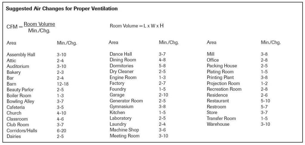
We are trying to do two things at the same time, sorta like chewing gum and walking. The first thing is to provide
ventilation for the plants living in the grow chamber. The second is to remove the heap of heat generated from our lighting.
This chart gives some recommended ventilation rates for common applications. I recommend 5 Minutes per Air Change and no more than 1-2 MpAC to keep stress down on the plants. High airflow rates cause excessive dehydration which is hard on the plants.
***********************************************************************************************
COMPARISON OF CABINET DESIGNS
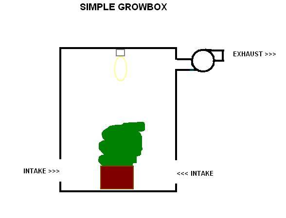
1. Simple Cab - one chamber, no scrubbers or restrictions to airflow.
CFM = 3.16*Watts/deltaT
where deltaT = 10 *F
Intake Area = 2 x Exhaust Area
Fans - Axial/Computer Fans due to minimal pressure loss
Example: A 400 W HPS in a 3 x 3 x 4 cabinet needs 126 CFM of cooling for a 10*F temp rise above room temperature.
The 36 cu ft cabinet is ventilated at over 3 Air Changes Per Minute.
Pro:
Easy to build
Fans - axial
Con:
plants stink up the place
plants are stressed by too much airflow at 3 ACpM.
The plants only need 5 Minutes per Air Changes (MpAC). That's 0.2 Air Changes per Minute (ACpM).
For you hydro guys, this means more rez changes and nute swings because the plants will be drinking alot to keep
up with the dehydration caused by living in a wind tunnel.
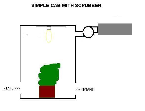
2. Simple Cab with Scrubber
CFM = 3.16*(Total Watts)/deltaT
where deltaT = 10 *F
Intake Area = 2 x Exhaust Area
Fans - Blower or Inline for high pressure drop across scrubber
Example: A 400 W HPS in a 3 x 3 x 4 cabinet needs 126 CFM of cooling for a 10*F temp rise above room temperature.
The 36 cuft cabinet is ventilated at over 3 ACpM. The hard part is to match an oversized fan/scrubber combination to get the right airflow.
This design and the simple growbox have cooling requirements that exceed the ventilation requirements of the growchamber by at least 15x. Way too much stress on the plants by living in a wind tunnel.
Pros:
single fan design less equipment to purchase
Cons:
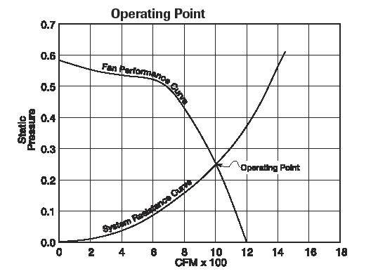
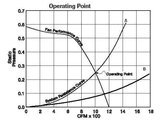
Fan operates at 50% or less airflow due to large pressure drop across scrubber
High SP requires a Centrifugal Blower, won't work with Axial fans
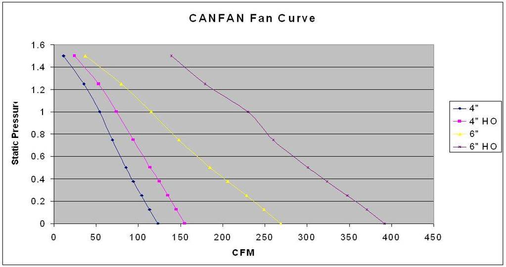
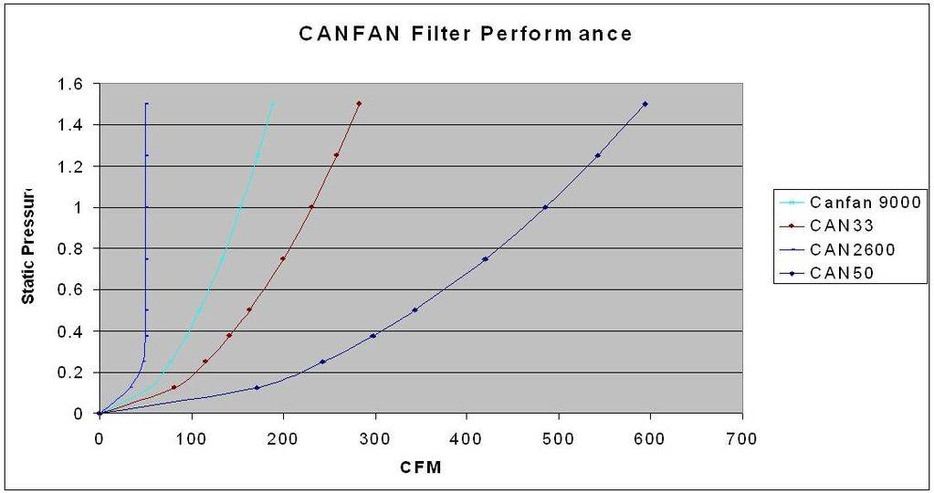
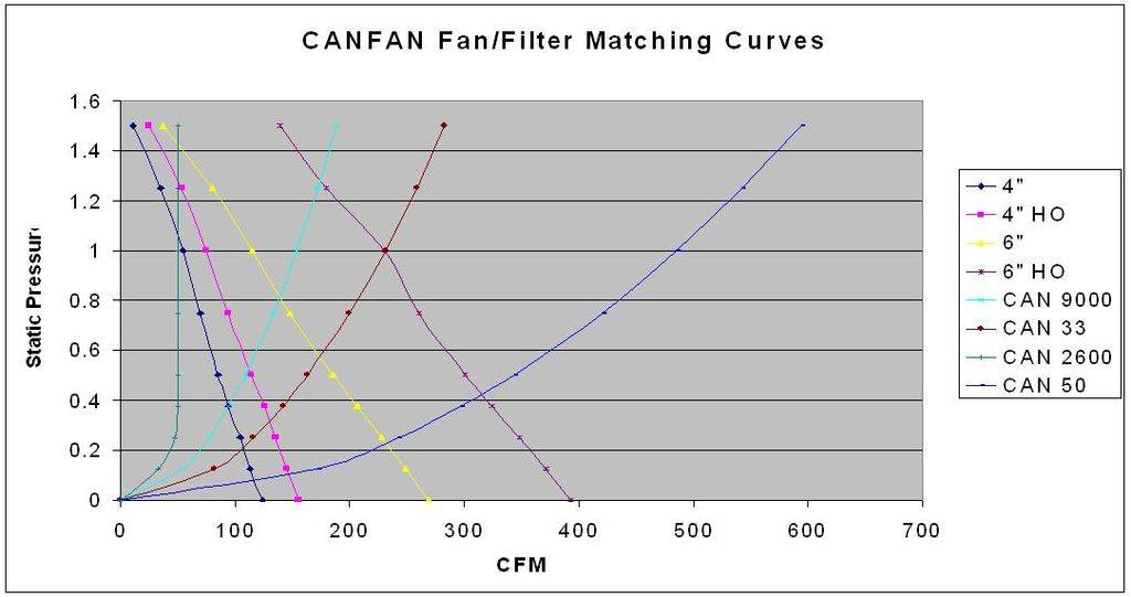
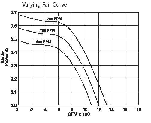
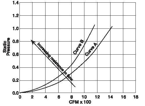
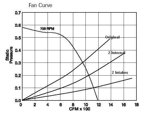
Fan/Filter Curves are needed to determine working airflow
Scrubber is many times larger than Ventilation specs to get light cooling airflow
many restrictions in multi chamber designs require special attention to intakes and intrachamber airflow
high airflow for to cool lights creates stress on plants
high airflow through scrubber reduces effectiveness
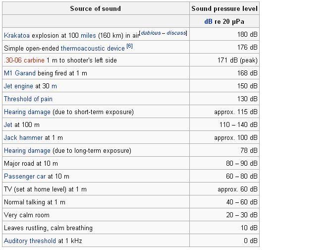
Centrifugal Blower and Inline Fans are very noisy 60-70 db
3. Simple Cab with CoolTube/Ventilated Hood and Inline Scrubber
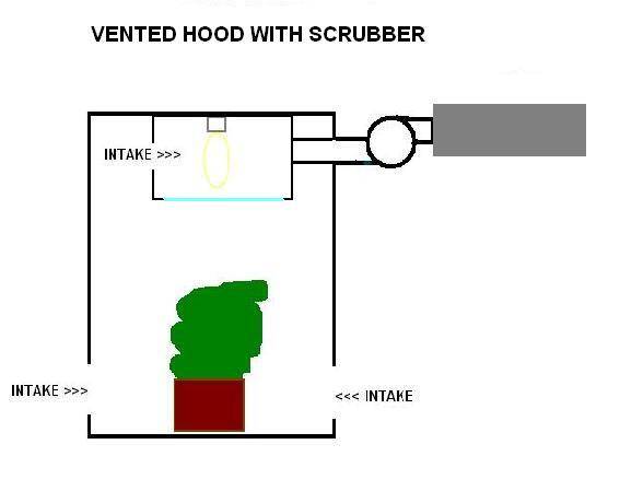
CFM = 3.16*(Total Watts)/deltaT
where deltaT = 20 to 30 for cooltube
Intake Area = 2 x Exhaust Area
Fans - Blower or Inline for high pressure drop across scrubber
Example: A 400 W HPS in a 3 x 3 x 4 cabinet needs 63 - 42 CFM of cooling for a 20-30*F temp rise in the exhaust temps with a 1-2 *F rise in the growbox.
The 36 cuft cabinet is ventilated at 2 ACpM. The hard part is to match an oversized fan/scrubber combination to get the right airflow.
The cooltube design is a big improvement over the Simple and Simple cab with Scrubber designs as the overall airflow is considerably less. However 2 ACpM is still 10x over what the plants need and will stress out the plants from excessive airflow.
Pros:
single fan design means less equipment to purchase
Cooltube/Ventilated Hood improves cooling significantly by trapping most of the heat in the hood
Less airflow through the grow chamber compared to the above designs but still high.
Cons:
Fan operates at 50% or less airflow due to large pressure drop across scrubber
High SP requires a Centrifugal Blower, won't work with Axial fans
Fan/Filter Curves are needed to determine working airflow
Scrubber is many times larger than Ventilation specs to get light cooling airflow
many restrictions in multi chamber designs require special attention to intakes and intrachamber airflow
high airflow for to cool lights creates stress on plants where only 0.2 ACpM is needed
high airflow through scrubber reduces effectiveness
Centrifugal Blower and Inline Fans are very noisy 60-70 db
4. Two Stage Cooling/Ventilation with cooltube and scrubber
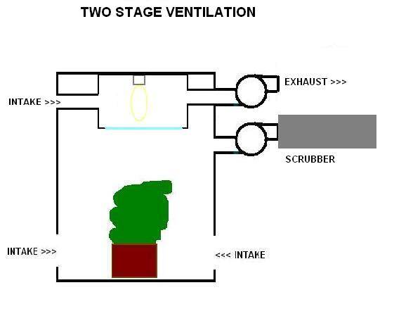
LIGHTING CFM = 3.16*(Total Watts)/deltaT
where deltaT = 20 to 30 *F
VENTILATION = 1 - 5 MpAC (Minutes per Air Change) or 0.2 to 1 Air Change Per Minute (ACpM)
Intake Area = 2 x Exhaust Area for EACH section
Fans - Axial for Lighting maximum airflow, minimal pressure loss
Small blower, inline or axial for scrubber
Example: A 400 W HPS in a 3 x 3 x 4 cabinet with a ventilated hood needs 63 - 42 CFM of cooling for a 20-30*F temp rise in the exhaust temps with a 1-2 *F rise in the growbox. 5 Minutes between Air Changes requires only 7 CFM through the scrubber.
Pros:
unrestricted airflow through lighting allows fan to operate at maximum rated flow
low air flow rates allow for smallest scrubber
use of less expensive fans as design is more efficient
Lighting exhaust deltaT can be 20-30*F while maintaining low grow chamber temps
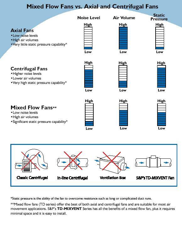
Much quieter as axial fans operate at 20-30 db compared to 60-70 for centrifugal fans
Cons:
more equipment
more intake and exhausts require more light proofing
ventilation design is more complex
5. Multi Chamber Designs
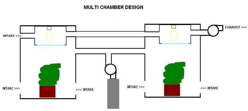
LIGHTING CFM = 3.16*(Total Watts)/deltaT
where deltaT = 20 to 30 *F per ventilated hood
Rule of thumb: 20*F temp rise for no more that 4 hoods chained together for a combined rise of 80*F
VENTILATION = 1 - 5 Min/Ch (Minutes per Air Changes)
Intake Area = 2 x Exhaust Area for EACH section
Fans - Axial for Lighting maximum airflow, minimal pressure loss
Small blower, inline or axial for scrubber
Example: Two 3 x 3 x 4 cabinets with a 400 watt HPS with a ventilated hood needs 63 - 42 CFM of cooling for a 20-30*F temp rise in the exhaust temps of each hood for a total of 40* to 60* temp rise with a 1-2 *F rise in the growbox. 5 Minutes between Air Changes requires only 14 CFM through the scrubber.
Pros:
unrestricted airflow through lighting allows fan to operate at maximum rated flow
low air flow rates allow for smallest scrubber
use of less expensive fans as design is more efficient
Lighting exhaust deltaT can be 20-30*F while maintaining low grow chamber temps
Much quieter as axial fans operate at 20-30 db compared to 60-70 for centrifugal fans
Cons:
more equipment
more intake and exhausts require more light proofing
ventilation design is more complex
Ventilation Chart
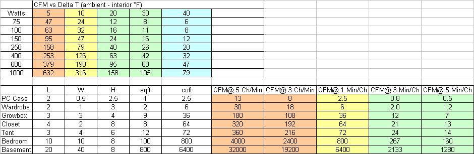
RECOMMENDED SPECIFICATIONS FOR GROWBOXES:
Simple Cabinet - airflow to maintain temperature within 10*F of ambient
Cool Tube or Ventilated Hood - exhaust air temp 20 - 30 *F. Hoods can be connected together to a common fan at 20 *F rise per hood, no more than 4 hoods for a total rise of 80 *F.
Grow Chamber Ventilation - 1 to 5 Minutes per Air Change. This is different for every type of light and setup. The more heat that is removed using a cool tube or ventilated heat means you can drop the grow chamber ventilation down further. The plants don't need very much air exchange and over 1 ACpM will cause unnecessary stress.
You will see a variety of equipment used to ventilate growboxes, tents and rooms. My recommendations are to put your money into a cool tube or a ventilated hood. Cooling a bare bulb with a centrifigal fan and scrubber combo is a big waste of money.
There's no need to scrub your light cooling air in a well designed system.
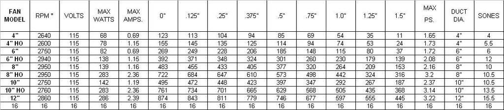
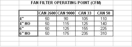
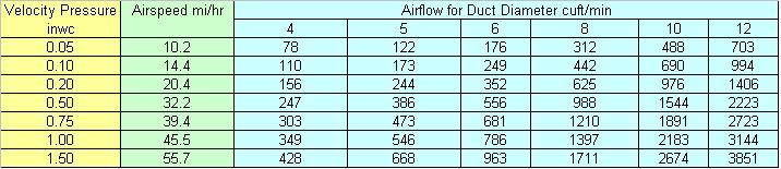
I'm going to show this handy chart again that show Air Flow Rates for Common Bulb Sizes. This chart is useful in two ways. For the cabinet builder, find your bulb size and the amibient temp rise you want and get the air flow needed off the chart.
INTAKE SIZING
Getting the intakes right is the biggest challenge in setting up a growbox. The intake area needs to be at least equal to the exhaust area and up to 2x to reduce losses.
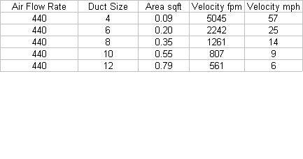
A = pi * (radius)^2 = (pi *diameter)^2/4
Areas for common duct and pipe sizes
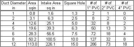
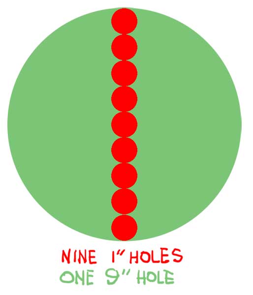
Thanks to Freezerboy for the nice picture. This is a common mistake when using a number of small holes to equal one big one. The only solution is to calculate the area for the big hole and divide by the AREA of the smaller holes to get the number of small holes needed.
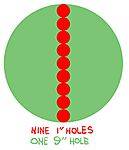
In this case one 9" hole needs 80 x 1" holes to be equivalent.
I'd like to point out that making one big hole is better than a bunch of little holes as each little hole has it's own Vena Contracta losses which do add up.
How to Check Your Cabinet for Proper Ventilation
For they guy wanting to know how well his cabinet is working, you can get the EFFECTIVE AIR FLOW rate from this chart. Here's how to do it. Measure the temperature of your exhaust air and subtract the ambient temperature to get the temperature rise number. Use the bulb size line and temperature rise to get the EFFECTIVE AIR FLOW RATE.
For example, a 250 W HPS lamp in a growbox with 90*F exhaust in a 70*F room is operating with 40 CMF of effective airflow.
as you all know if the women don't find you handsome, they better find you handy...
I've got some background experience and have wanted to do a good write up for a while.
I have a collection of source material and will be cutting and pasting from it with a more detailed explanation that is more relevent to our hobby, building cabinets.
One of the lads in the Lodge says that growing leads to carpentry. I'm sure he's right.
***********************************************************************************************
We are trying to do two things at the same time, sorta like chewing gum and walking. The first thing is to provide
ventilation for the plants living in the grow chamber. The second is to remove the heap of heat generated from our lighting.
This chart gives some recommended ventilation rates for common applications. I recommend 5 Minutes per Air Change and no more than 1-2 MpAC to keep stress down on the plants. High airflow rates cause excessive dehydration which is hard on the plants.
***********************************************************************************************
COMPARISON OF CABINET DESIGNS
1. Simple Cab - one chamber, no scrubbers or restrictions to airflow.
CFM = 3.16*Watts/deltaT
where deltaT = 10 *F
Intake Area = 2 x Exhaust Area
Fans - Axial/Computer Fans due to minimal pressure loss
Example: A 400 W HPS in a 3 x 3 x 4 cabinet needs 126 CFM of cooling for a 10*F temp rise above room temperature.
The 36 cu ft cabinet is ventilated at over 3 Air Changes Per Minute.
Pro:
Easy to build
Fans - axial
Con:
plants stink up the place
plants are stressed by too much airflow at 3 ACpM.
The plants only need 5 Minutes per Air Changes (MpAC). That's 0.2 Air Changes per Minute (ACpM).
For you hydro guys, this means more rez changes and nute swings because the plants will be drinking alot to keep
up with the dehydration caused by living in a wind tunnel.
2. Simple Cab with Scrubber
CFM = 3.16*(Total Watts)/deltaT
where deltaT = 10 *F
Intake Area = 2 x Exhaust Area
Fans - Blower or Inline for high pressure drop across scrubber
Example: A 400 W HPS in a 3 x 3 x 4 cabinet needs 126 CFM of cooling for a 10*F temp rise above room temperature.
The 36 cuft cabinet is ventilated at over 3 ACpM. The hard part is to match an oversized fan/scrubber combination to get the right airflow.
This design and the simple growbox have cooling requirements that exceed the ventilation requirements of the growchamber by at least 15x. Way too much stress on the plants by living in a wind tunnel.
Pros:
single fan design less equipment to purchase
Cons:
Fan operates at 50% or less airflow due to large pressure drop across scrubber
High SP requires a Centrifugal Blower, won't work with Axial fans
Fan/Filter Curves are needed to determine working airflow
Scrubber is many times larger than Ventilation specs to get light cooling airflow
many restrictions in multi chamber designs require special attention to intakes and intrachamber airflow
high airflow for to cool lights creates stress on plants
high airflow through scrubber reduces effectiveness
Centrifugal Blower and Inline Fans are very noisy 60-70 db
3. Simple Cab with CoolTube/Ventilated Hood and Inline Scrubber
CFM = 3.16*(Total Watts)/deltaT
where deltaT = 20 to 30 for cooltube
Intake Area = 2 x Exhaust Area
Fans - Blower or Inline for high pressure drop across scrubber
Example: A 400 W HPS in a 3 x 3 x 4 cabinet needs 63 - 42 CFM of cooling for a 20-30*F temp rise in the exhaust temps with a 1-2 *F rise in the growbox.
The 36 cuft cabinet is ventilated at 2 ACpM. The hard part is to match an oversized fan/scrubber combination to get the right airflow.
The cooltube design is a big improvement over the Simple and Simple cab with Scrubber designs as the overall airflow is considerably less. However 2 ACpM is still 10x over what the plants need and will stress out the plants from excessive airflow.
Pros:
single fan design means less equipment to purchase
Cooltube/Ventilated Hood improves cooling significantly by trapping most of the heat in the hood
Less airflow through the grow chamber compared to the above designs but still high.
Cons:
Fan operates at 50% or less airflow due to large pressure drop across scrubber
High SP requires a Centrifugal Blower, won't work with Axial fans
Fan/Filter Curves are needed to determine working airflow
Scrubber is many times larger than Ventilation specs to get light cooling airflow
many restrictions in multi chamber designs require special attention to intakes and intrachamber airflow
high airflow for to cool lights creates stress on plants where only 0.2 ACpM is needed
high airflow through scrubber reduces effectiveness
Centrifugal Blower and Inline Fans are very noisy 60-70 db
4. Two Stage Cooling/Ventilation with cooltube and scrubber
LIGHTING CFM = 3.16*(Total Watts)/deltaT
where deltaT = 20 to 30 *F
VENTILATION = 1 - 5 MpAC (Minutes per Air Change) or 0.2 to 1 Air Change Per Minute (ACpM)
Intake Area = 2 x Exhaust Area for EACH section
Fans - Axial for Lighting maximum airflow, minimal pressure loss
Small blower, inline or axial for scrubber
Example: A 400 W HPS in a 3 x 3 x 4 cabinet with a ventilated hood needs 63 - 42 CFM of cooling for a 20-30*F temp rise in the exhaust temps with a 1-2 *F rise in the growbox. 5 Minutes between Air Changes requires only 7 CFM through the scrubber.
Pros:
unrestricted airflow through lighting allows fan to operate at maximum rated flow
low air flow rates allow for smallest scrubber
use of less expensive fans as design is more efficient
Lighting exhaust deltaT can be 20-30*F while maintaining low grow chamber temps
Much quieter as axial fans operate at 20-30 db compared to 60-70 for centrifugal fans
Cons:
more equipment
more intake and exhausts require more light proofing
ventilation design is more complex
5. Multi Chamber Designs
LIGHTING CFM = 3.16*(Total Watts)/deltaT
where deltaT = 20 to 30 *F per ventilated hood
Rule of thumb: 20*F temp rise for no more that 4 hoods chained together for a combined rise of 80*F
VENTILATION = 1 - 5 Min/Ch (Minutes per Air Changes)
Intake Area = 2 x Exhaust Area for EACH section
Fans - Axial for Lighting maximum airflow, minimal pressure loss
Small blower, inline or axial for scrubber
Example: Two 3 x 3 x 4 cabinets with a 400 watt HPS with a ventilated hood needs 63 - 42 CFM of cooling for a 20-30*F temp rise in the exhaust temps of each hood for a total of 40* to 60* temp rise with a 1-2 *F rise in the growbox. 5 Minutes between Air Changes requires only 14 CFM through the scrubber.
Pros:
unrestricted airflow through lighting allows fan to operate at maximum rated flow
low air flow rates allow for smallest scrubber
use of less expensive fans as design is more efficient
Lighting exhaust deltaT can be 20-30*F while maintaining low grow chamber temps
Much quieter as axial fans operate at 20-30 db compared to 60-70 for centrifugal fans
Cons:
more equipment
more intake and exhausts require more light proofing
ventilation design is more complex
Ventilation Chart
RECOMMENDED SPECIFICATIONS FOR GROWBOXES:
Simple Cabinet - airflow to maintain temperature within 10*F of ambient
Cool Tube or Ventilated Hood - exhaust air temp 20 - 30 *F. Hoods can be connected together to a common fan at 20 *F rise per hood, no more than 4 hoods for a total rise of 80 *F.
Grow Chamber Ventilation - 1 to 5 Minutes per Air Change. This is different for every type of light and setup. The more heat that is removed using a cool tube or ventilated heat means you can drop the grow chamber ventilation down further. The plants don't need very much air exchange and over 1 ACpM will cause unnecessary stress.
You will see a variety of equipment used to ventilate growboxes, tents and rooms. My recommendations are to put your money into a cool tube or a ventilated hood. Cooling a bare bulb with a centrifigal fan and scrubber combo is a big waste of money.
There's no need to scrub your light cooling air in a well designed system.
I'm going to show this handy chart again that show Air Flow Rates for Common Bulb Sizes. This chart is useful in two ways. For the cabinet builder, find your bulb size and the amibient temp rise you want and get the air flow needed off the chart.
INTAKE SIZING
Getting the intakes right is the biggest challenge in setting up a growbox. The intake area needs to be at least equal to the exhaust area and up to 2x to reduce losses.
A = pi * (radius)^2 = (pi *diameter)^2/4
Areas for common duct and pipe sizes
Thanks to Freezerboy for the nice picture. This is a common mistake when using a number of small holes to equal one big one. The only solution is to calculate the area for the big hole and divide by the AREA of the smaller holes to get the number of small holes needed.
In this case one 9" hole needs 80 x 1" holes to be equivalent.
I'd like to point out that making one big hole is better than a bunch of little holes as each little hole has it's own Vena Contracta losses which do add up.
How to Check Your Cabinet for Proper Ventilation
For they guy wanting to know how well his cabinet is working, you can get the EFFECTIVE AIR FLOW rate from this chart. Here's how to do it. Measure the temperature of your exhaust air and subtract the ambient temperature to get the temperature rise number. Use the bulb size line and temperature rise to get the EFFECTIVE AIR FLOW RATE.
For example, a 250 W HPS lamp in a growbox with 90*F exhaust in a 70*F room is operating with 40 CMF of effective airflow.
Last edited:


 excuse my manors.