
-
Happy Birthday ICMag! Been 20 years since Gypsy Nirvana created the forum! We are celebrating with a 4/20 Giveaway and by launching a new Patreon tier called "420club". You can read more here.
-
Important notice: ICMag's T.O.U. has been updated. Please review it here. For your convenience, it is also available in the main forum menu, under 'Quick Links"!
You are using an out of date browser. It may not display this or other websites correctly.
You should upgrade or use an alternative browser.
You should upgrade or use an alternative browser.
Ogre's DIY Ebb & Grow / Multi-Flow Controller Tutorial
- Thread starter OgreSeeker
- Start date
hey guys great thread as far as a multi controller without two timers goes. Im interested in building a drip irrigation system for a 180 plant, soil grow. Im considering taking a page out of this tutorial as far as my ebb resovouier goes, most drip irrigation stores only sell the tubing/tape and fittings, not the actual resoiver. What would be the best way to go about building the res.? And would you reccommend putting regular waterproof tape on the drip holes considering were only working with '12 spaces tops in the line, while working with roughly 2 1/2 sq. ft. wide 5 gall. grow bags? One last question will the PPM fall at any point of the line, similar to PSI? I appreciate any help???? CMR..
I assume you've already solved your problem already, C-man, but if not, check this out. They go all the way to 500 gals:^bump^ for an answer to my question..
http://www.tank-depot.com/product.aspx?id=277
I'm about to build up my control bucket, I bought the aquahub kit. In their instructions they give directions for using 2 timers but I'm going to try using a paragon digital SPDT timer, I don't see why the drain side of the system couldn't always be energized if it's controlled with float switches?
sorry if this is a little off topic
Does anyone know of a where I could obtain a suitable replacement relay for a C.A.P ebb and gro controller, it appears that the relay for routing power to the fill pump has become dodgy only clicking over 1/3 of the time
I have found the exact replacement but I would have to order no less then 1000 of them from china, C.A.P will not send me a replacement relay unless I send in my unit which has been modified to use a 5 gallon bucket and have a 3ft
I believe its a 10A / 220VAC, 28VDC relay but beyond that I am not sure.
any help on this would be most appreciated.
Thanks
Help!!! just got done with my controller and it doesn't work. when the timer kicks on one of the relays will make a loud buzzing sound and you can see sparks! when i lift up the bottom float the other relay will buzz. took it apart 5 times now and im sure the wiring is where it should be. the only thing thats different is im using a 20amp 125v standard single outlet not the 15amp 120v, but that shouldnt be the problem should it? maybe the relays are bad? what do you guys think?
Help!!! just got done with my controller and it doesn't work. when the timer kicks on one of the relays will make a loud buzzing sound and you can see sparks! when i lift up the bottom float the other relay will buzz. took it apart 5 times now and im sure the wiring is where it should be. the only thing thats different is im using a 20amp 125v standard single outlet not the 15amp 120v, but that shouldnt be the problem should it? maybe the relays are bad? what do you guys think?
sdeg6, if your seeing sparks chances are you've got some wires making contact with each other, or they're wired incorrectly. You said the relays are buzzing so I bet it's probably one of those connections giving you headaches.
Those relays are so small, compared to a standard 12v auto relay, that you have to be extremely careful when making your connections. If you're using the spade connects take a small pair of pliers and pinch them a little so they stay firmly attached to the relay post(s) and don't shift around a lot. I also ran a few passes of electrical tape around the base of the relays when I was done.
Hope this helps.
I finished building my aquahub kit, works great. One thing I found was the lowest level float can be mounted way lower. I'm using a pump that goes down to 1/8 of an inch, so drilled my hole for the low level switch 1 1/8in up the bucket. I have the float angled so it works properly.
sundancer245
New member
k...built the controller, question: how exactly do you set one timer to run the whole thing...this is the one thing i havent seen on here is how to set up the timer can someone please help?!?!?
can someone please help?!?!?
R
rmcc-luke
double post
Last edited:
R
rmcc-luke
Builing this system tomorrow - would like to go digital on the timer
Builing this system tomorrow - would like to go digital on the timer
DANK said:
i am going to go try building one to your specs with a digital timer and a third relay. . . . woooo
Luke asks:
did you get this figured out? I haven't been able to decipher the previous post. please post a diag/picture of the wiring so we can all move to digital timers.
Ogre: thank you and the others for this DIY - you have save me hundreds and now I can build this system according to my needs (3/4 - 6 feeds, 6 buckets!)
yamaha_1fan : thank you for the digital timer add on so that we can set by the minute times.
Dank: thank you in advance for any help you (or yamaha) can offer with the wiring of the digital timer.
Confused but excited about this project
Luke
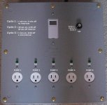
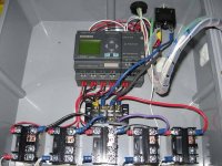
This controller was built to control 5 pumps with several timing cycles controlled by a PLC. None of the pumps are all on at once, only one pump at a time. When the reservoir refills from the tables, the next pump turns on. Moisture sensors, solenoid valves, float-switches, photocells, etc can all be added to add more versatility to the controller.
Attachments
GoldenGoblin
New member
Digital Timers?
Digital Timers?
Bump
Digital Timers?
Bump
DANK said:
i am going to go try building one to your specs with a digital timer and a third relay. . . . woooo
Luke asks:
did you get this figured out? I haven't been able to decipher the previous post. please post a diag/picture of the wiring so we can all move to digital timers.
Ogre: thank you and the others for this DIY - you have save me hundreds and now I can build this system according to my needs (3/4 - 6 feeds, 6 buckets!)
yamaha_1fan : thank you for the digital timer add on so that we can set by the minute times.
Dank: thank you in advance for any help you (or yamaha) can offer with the wiring of the digital timer.
Confused but excited about this project
Luke
R
rmcc-luke

Bump
Thanks man,
I have both a digital and the mech timer recommended by ogre. I guess if no one responds I'm moving forward with the mech.
I have also been looking into a way to use my CAP CGC1's hyrdo pump AC output to trigger the pumps but I don't know how that would work yet. I think once I have assembled the system and have it running I can start hacking on it to figure out cool new ways to integrate it into CGC.
samba
Active member
Hello
I'm a bit of an idiot with electronics and shit so i was thinking of this multi-controller and how to make on without any skills...
Came up with this
So,
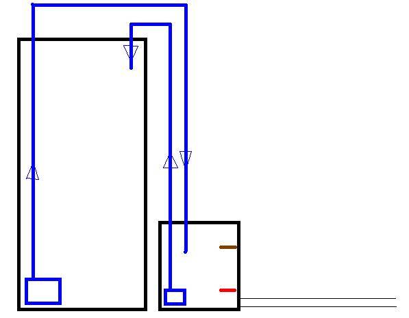
Big black box = REZ
Small black box controller bucket
Big blue box = big pump
Small blue box = small pump
Blue line = tubing
Red line = No.1 float valve (FV)
Brown line = No.2 float valve (FV)
So, this is how I taught it would work (hopefully work)
Big pump on a timer and would cut power when water level higher than No.2 FV
Small pump on 24/7 and would cut power off when water level lower than No.1 FV
So, when the timer comes on the big pump activates, pumping to controller, in some time the small pump would activate to, as the water level rises on controller, but as its smaller than the big pump, so water level would keep rising. Then water level rises to No.2 FV and cuts of power to big pump. Small pump keeps pumping until it reaches No.1 FV and power is cut of from small pump...
You think this would work? I't would be good for the more simple ones here, like me.
Ps. you would need to have a "air-hole" in the highest point in the big pump water line, so gravity wont keep sucking water when pump goes off
I'm a bit of an idiot with electronics and shit so i was thinking of this multi-controller and how to make on without any skills...
Came up with this
So,
Big black box = REZ
Small black box controller bucket
Big blue box = big pump
Small blue box = small pump
Blue line = tubing
Red line = No.1 float valve (FV)
Brown line = No.2 float valve (FV)
So, this is how I taught it would work (hopefully work)
Big pump on a timer and would cut power when water level higher than No.2 FV
Small pump on 24/7 and would cut power off when water level lower than No.1 FV
So, when the timer comes on the big pump activates, pumping to controller, in some time the small pump would activate to, as the water level rises on controller, but as its smaller than the big pump, so water level would keep rising. Then water level rises to No.2 FV and cuts of power to big pump. Small pump keeps pumping until it reaches No.1 FV and power is cut of from small pump...
You think this would work? I't would be good for the more simple ones here, like me.
Ps. you would need to have a "air-hole" in the highest point in the big pump water line, so gravity wont keep sucking water when pump goes off

