What's new
  • Happy Birthday ICMag! Been 20 years since Gypsy Nirvana created the forum! We are celebrating with a 4/20 Giveaway and by launching a new Patreon tier called "420club". You can read more here.
  • Important notice: ICMag's T.O.U. has been updated. Please review it here. For your convenience, it is also available in the main forum menu, under 'Quick Links"!

Water Cooling LED's Discussion Thread

Drop That Sound

Well-known member
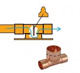
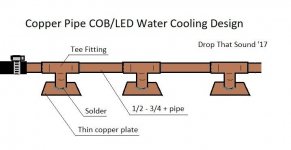
f-e I like the way you think. I though about flattening (flat-earthening?) some copper pipe too, but then I thought a little harder and came up with this design below. I have all the parts to make it just never tried yet. Even have the copper sheeting, which I would hope simply soldering to a tee fitting would hold up.

Copper always seems to kink and develop cracks, I wouldn't hammer on it, but could still be done if done right. Maybe you could stick a small square block (like a 2"L x 3/4" x 3/4 into the center of a short length of say 1" diameter pipe, you could squeeze it with a vice. Or flatten one side of a rod that fits. Then pop it out, and put that flattened piece in between 2 reducing couplers.

Your other designs look like they would work well. Wish copper stuff wasn't so spendy! I got lots of pipe/fittings/scraps to play with and test on, if I ever had the time.


Good idea about using just a corrosion inhibitor instead of coolant. At least i think so, hopefully it would mix into the water and still do its job.

Oil might work, as in mineral oil, etc. If you did spring a leak it wouldn't mess with the electronics, but would be a pain to clean up. I've seen vids where guys submerge COB's directly into the oil (usually PCs), even in jars so the light shines out the bottom. Not exactly something I would want in my rooms but "cool" none the less.
 

Attachments

  • CopperWC.jpg
    CopperWC.jpg
    22.9 KB · Views: 25
Last edited:

f-e

Well-known member
Mentor
Veteran
I like it. It makes me think. And your copywrite is out of date, so game on :)

This reduction fitting might be better, and further improved by cutting the larger branch off almost completely. So the flow in your main line has more interaction with the sole plate your led bonds to.
https://proxy.duckduckgo.com/iu/?u=...content/uploads/2013/11/528e3e1fe9b29.jpg&f=1

If you look inside a cpu cooler, they have channels to guide the coolant back and forth (oils never crossed my mind, but are similar to air or glycol). Water will take the easiest path, which isn't rubbing shoulders with stationary metal. The channels ensure water keeps moving where we want it to go. Picking up heat from the entire cpu surface. In Victorian times, people worked in large underground reservoirs simply mixing the water around. Otherwise it would stagnate in the corners.

If we want to use this design, we may find it offers very localised cooling. Not an even distribution. So the cob will need to get it's heat out at that spot. This means making the sole plate thicker. Imagine if the plate was a foil, it would have so few thermal paths, they would all be in gridlock, and the hot edges of the cob could fry. The thicker plate offers more routes, so less gridlock for the energy trying to move.

I'm sure I have seen fittings where water entering the larger port, doesn't hammer the side wall, before going left or right. But instead, see's more of a Y shaped choice. Such a fitting would cause useful turbulence.


I'm really just chucking ideas around. Many of which would scale up to 8' long units, in multiples. My very first drawing was small parts to enable builds of any dimension, just bolting them to copper pipes we can all buy. So I quickly dismissed the cpu coolers. Thinking in terms of 'dozens' would be a mess of plumbing that no warehouse would take on. Part of designing is assassinating every idea, as you add your own twist. I think for the 6 light microgrow, the cpu coolers might not be that bad an idea. A whole damn industry is behind them, and it's only a multiple of 6. Each capable of keeping 100w cpu's under 50c measured on chip.


That's a plumbing arrangement to keep an equal flow to all blocks.
If we look at the coolant leaving the far left block, it has two routes to reach off the page. Route A and route B. It will use both, and the two lengths can be added together for pressure drop calculations we don't need. Now move to any of the other 5 blocks. It also has two routes, which added together, are exactly the same as the first block. Its the same for all 6 blocks. You could put one block in the next room, and still the plumbing resistance stays the same at all the blocks. There are a few rules. The red bits should be fairly equal lengths, and the blocks should all be the same height.

I have drawn a little image where a wall could be used to divert any leaks away from the cob.

These ben&jerry's cobs need 3 connections, not two. They must be grounded, which is done on the block. It's not really them you're grounding, but the surrounding area. It's marked on the edge of the board. This will be 'interesting' to attach. You may have to put a jubilee clip round the block.
I also suggest a 15mA rcd is used for your lighting in these dodgy circumstances. You can buy one in a box for about £20, and chop an extension lead in half to put a plug and outlet on it. I can detail it further if required. 15mA is about right for wet hands, while your home is likely 30mA with no power where water is present.

It's a bit rough really. Exposed mains chips, glued in place, with water and no decent ground points.
But then, the long blocks, jubilee clipped to some sturdy metal support system, might keep the experiment on track. It's not saving money though.
 

Drop That Sound

Well-known member
Ya a loop definitely helps distribute the flow to multiple blocks, or even spray nozzles in an aero system for that matter.


Hows this for V2? The scrap doesn't have to fit perfectly, but good enough to channel most the coolant down to the plate. Tacked on the inside with a few blobs of solder. Using that reducing tee fitting not only has more surface area to the plate, but also larger diameter for more solder to go around, for a better bond. Notice I flared the cut end out a bit too, for even a little more area ;)
 

Attachments

  • copper cooling tube block v2.jpg
    copper cooling tube block v2.jpg
    15.3 KB · Views: 27

St. Phatty

Active member
I can't even use my 500 watt LED panel to dry Cannabis. The bulbs are too efficient !

Maybe if I put the Cannabis in the light, since it's sort of like weak sun-light.

My own fooling around with COB's was snafu'd. Ended up going to Screw in Lights.
 

f-e

Well-known member
Mentor
Veteran
I just lost a post that took two hours, then another.

I have to go out soon, but here is a bit..


The idea of a flap in the fitting seems good. It could be an interference fit. A lot of localised soldering is going to mean it's all wet at the same time. It will also mean using a thick sole, to resist warping. This thick sole may mean a 28mm water contact area is enough for a 400mm2 led. I have copper sponge on my mind, like used in distillation columns. Also, if a non linear appearance across the room is ok, then the Tee could be positioned so the supply water is pointing at the sole. Here is a fitting that may help with that https://www.ebay.com/sch/i.html?_from=R40&_trksid=m570.l1313&_nkw=272714004329&_sacat=0


I did a few thermal calculations. a 40mm2 tube would loose 50w per meter, gaining just 25c above ambient. Sticking with round pipes that have cheap insulation options makes sense. I have lost the rest and I'm getting ready for work so just offloading what I remember.

I did a few pics.

A 10mm x 50mm x 50mm copper plate is about £10. Ouch. But a 28mm contact area across the sole is appealing. Maybe get some of that copper scouring pad in there.

Really gotta get my mind in another state now... :)
 

Douglas.Curtis

Autistic Diplomat in Training
Awesome details, the plumbing for even resistance is gold. :) I know a little about the subject and your addition is very clear. Thank you!

As for the ground points, I missed this bit and it wasn't mentioned in the literature. I haven't read circuits for years so I missed it on the chip as well. lol (Edit: I've looked and still don't see any reference to ground on the board?)

What's the end result of everyone using these with 2 leads on an aluminum heat sink?

Would grounding each cooling channel work, as long as an electrical bond is made between the chip base and channel?
 

f-e

Well-known member
Mentor
Veteran
Not all my smart cobs are the same. Quite a few have the ground info wrote on the edge, along with type numbers and voltage. In any case, there is scope for a solder pad coming adrift and touching what's likely metal beside it. Or, you simply touching it yourself. Having connections out in the open how they are, should be addressed somehow, for sure. I didn't say gaffer tape. No I didn't. It's not true.


I just had a eureka moment, that can't cover the fact it took so long.

Linear led's. If the cooling system is linear, then why would you try and attach square soles. Long thin pipes, call for long thin led's.
https://www.ebay.com/itm/30W-50W-70...22304118639?hash=item33c25ba76f:rk:4:pf:0&var
The strip on the 30 and 50w one's is just 14mm wide.
The 70w 16mm and the 150w just 20mm.
That's square copper pipe of 20mm, with a sole plate soldered or even glued to it. Not a 10mm thick one either.

This is the kind of thing I almost have laying around the house.
 

f-e

Well-known member
Mentor
Veteran
I can't even use my 500 watt LED panel to dry Cannabis. The bulbs are too efficient !

Maybe if I put the Cannabis in the light, since it's sort of like weak sun-light.

My own fooling around with COB's was snafu'd. Ended up going to Screw in Lights.

Many lamp designs give off light by getting something hot. So the primary emission can be radiant heat. This is why air cooling and even water jackets have real limitations for them.

The LED is different, and in fact radiates very little heat energy (IR). The wasted power leaves mostly through conduction. Well over half of it. Maybe over 75%.

Watt for Watt the bulk of the leds we use actually make more heat than the sodiums they are starting to replace. It just leaves by a different mechanism. At least, it leaves into the heatsink that way. The heatsink in turn might loose a lot by radiating it. Rather than convection or fan assisted air currents. It depends on it's design.

I'm not sure how your using your lights to dry a bit, but perhaps I have illuminated your issue.
 

Douglas.Curtis

Autistic Diplomat in Training
Not all my smart cobs are the same. Quite a few have the ground info wrote on the edge, along with type numbers and voltage.
Ok, I thought you meant the Ming & Ben chips. This makes sense now. :)

In any case, there is scope for a solder pad coming adrift and touching what's likely metal beside it. Or, you simply touching it yourself. Having connections out in the open how they are, should be addressed somehow, for sure.
Epoxy works great. :) Makes a nice protective layer, while also making a permanent bond between wire and chip. :) Two birds, one epoxy potting session.
I just had a eureka moment, that can't cover the fact it took so long.

Linear led's. If the cooling system is linear, then why would you try and attach square soles. Long thin pipes, call for long thin led's.
https://www.ebay.com/itm/30W-50W-70...22304118639?hash=item33c25ba76f:rk:4:pf:0&var
The strip on the 30 and 50w one's is just 14mm wide.
The 70w 16mm and the 150w just 20mm.
That's square copper pipe of 20mm, with a sole plate soldered or even glued to it. Not a 10mm thick one either.

This is the kind of thing I almost have laying around the house.
This is where I'm heading in the future. :) Good call. lol
 

f-e

Well-known member
Mentor
Veteran
My heat loss calculations are not what I wanted to see. To keep a 50w led around 50-60c, the contact area with the water needs to be about a square foot. I have looked at it a couple of ways, and found similar results.

Led's need that alloy there bonded to. The bond is one of the areas they have to really work on to advance led technology. Any less heat transfer than the alloy, is a fail. Alloy has that 200 whatsits thermal conductivity. Water just 0.6 so it's a 300:1 ratio. There is a lot of movement with various variables in play, but I think I just trashed my idea.

When I'm done with my green 20w cob, I will glue it to the bottom of a thin cake tin. Fill it with water, and see what happens.

I don't like math of this complexity. Any sum that involves letters not numbers is big bottom lip time. Swap them letters for a row of little pictures I have never seen, and I'm holding my head before even looking up what they mean. Shall we air cool them instead? lol

This year I expect to see led lights appear with vent hose attachments. Using slightly better fans, to send the air to the carbon filter directly. Using a PC fan, my 140w led takes in air at 18c and it leaves via ducting at 36c. Just a very gentle breeze.

But on topic.. I'm still drawing up plans.
 

Douglas.Curtis

Autistic Diplomat in Training
Is there a greater light to heat output when the chips are dimmed, or is it linear?

What is the input temp of the water you're using in your math? At this point I have no idea how much cooling can be easily/efficiently provided. lol If I had something which used water all day anyway, I could use it to keep a coil cold. The tap water seems to be cold all year round here.
 

Douglas.Curtis

Autistic Diplomat in Training
What about using long extruded aluminum heat sinks, then attaching an aluminum U-channel over top of it? Sealed together, they make a long, water-cooled heat sink when water is pumped through it. I'm thinking deep fins like this one here.

I'm mulling over ways to end-cap it efficiently, so water flows through all fins properly. Air bubbles are a known issue with water cooling. Cutting the heat sink at an angle would probably work. This would allow a small water gap in front of the fins, and a sloped surface to reduce turbulence.

Have to keep in mind, all additional resistance means needing additional pump pressure. Even messing around, I like to keep things efficient. lol
 

Drop That Sound

Well-known member
Ive always wanted to make a small scale aluminum foundry.. people give away aluminum car rims/scrap all the time around here.. pop and beer cans would take longer to aquire but could be used as fins if you used enough of them attached to blocks. I was wanting to make aluminum siding and roof shingles and a few other things. Just an idea if going into production.

Could make a mold for water channeling bars that slides right into one of those 2x1 tubes, with minimal machining. Also one for the caps set up for the fittings to be glued on the ends.. Seems like a good way to go if producing a quantity of linear 2x1 aluminum water blocks in your back yard.


On another topic, ive been saving tall arizona ice tea cans and used pvc sewer pipes to make heat recovery ventilators for my grow trailer. Multiple pvc/can cores with a manifold instead of 1 long tube. The units can be scaled up while only taking 4 inches of wall space, or even integrated into the wall itself!. Saving 1000's of dollars compared to a commercial HRV unit with a smaller cross flow cores using plates, etc.

I would love to integrate a water loop/radiator into my design somehow, and gives me even more incentive to play with a water cooling/heating system.

As of now I only plan to use a single res to cool 2 RDWC and an aero/nft/swc system all with one modded AC unit to chiller. Possibly hooking up icebox exchangers in the flower room to the same res too, or even geothermally into the creek. We got an excavator and i could dig a ditch for a loop as well. So many ideas, so little time these days :(
 

Drop That Sound

Well-known member
I was back reading through the screw-in LED thread, and seen a post where I asked about using just the PCBs that SIL's use and a seperate ballast, and clicked on the link from jonhova which led to your own post about remote ballasting.

And there it was: https://www.youtube.com/watch?v=IgRmZkZWHmM

A link from HuffnPufferfish with a guy that already water-cooled COBs with the 2x1 aluminum.

Did you miss that too? lol


I
 

Drop That Sound

Well-known member
Dude is cooling 3.2kw with 4 bars , I'm sure you can get away with .3kw on 3 bars that are a few inches shorter.

Said he paid 120 bucks for that thing?. Also says its not the right kind of lights for growing on a comment, which leads me to believe he doesn't know what he's even talking about, but pretty sure he could grow some fine plants if he hung it up like 12 feet over a large area!
 

f-e

Well-known member
Mentor
Veteran
You notice he doesn't use a driver. He rectifies the 120ac to give himself 170v, then puts a number of the 100w (actually 50w) chips in series. I need 10 citizen 1212's for my 379v rectified supply. It's been on my mind a while. Use a 'clean mains' type extension lead to avoid spikes, and it should work. You couldn't plumb 10 in series though, as uneven temps lead to uneven voltage. I thought up a few rough ways of current monitoring that could add a further led to reduce the power. Nothing great though.


I have found some little led 'barn' type lights.
https://www.ebay.com/itm/50W-220V-L...h=item2ac062839e:g:l8gAAOSwZjNbYRUE:rk:8:pf:0

Available at 30w 50w 80w and 100w, they consist of a linear array, smart chipped cob, placed in a typical barn shaped reflector.

Now I look at these completed units and think a few rivets and some thin alloy sheet... These must suck. But then, these are waterproof units, that won't cook if simply used as they are. But they are crying out for better cooling. If fixed along a cool tube of water, a lot of the heat energy would head that way. The top could be made flat, buy taking the rivets out, and moving the power flex. And assembling with thermal epoxy or plaster instead. You could even fix the lights to a square tube with U bolts. So they can be moved about.

While not entirely water cooled, a lot of the heat would head to the water. But you wouldn't fear turning the water off or down, when you did actually need some heat.

Using 100w variants, you may need just 4 per meter. So that's just two runs of pipe.

Refining the plumbing further, I would use 20mm2 but use two not just one. Put them together like a 20x40 tube with a center wall. To keep plumbing at one end, and the temperature similar at every fitting. As the water goes up one, and down the other.


I'm still looking at the copper pipe and T piece method. Using lots of 10w (or even 3w) cobs, straight off the mains electricity. The 380v I have is a lot of 9-10v leds, so is no small project. But site transformers give 55-0-55 and pc power supplies are a very well regulated 12v and 500w units cost $10. Maybe I should get this hefty 12v and use a number of voltage regulators, for batches of 10v leds. A pack of 10 3w cobs is just £1 and a 3w cob could be just glued to a round copper tube (if I'm feeling lucky)
 

Drop That Sound

Well-known member
I think the copper and Tee's, with a cheaper thin copper sole (like my drawings) then just bonded to a thicker aluminum plate could work good.

All the plumbing on one end with doubled up tubing would be nice!..

And for the 3w cobs, maybe you could slightly file a flatter surface onto a coupler , instead of the actual pipe itself for a more secure fit.


Off topic again but I been thinking lately about using free and flea market stainless steel pots ( with another plastic tub inside like a displacer so the water stays to the bottom and sides of the pot) in another bucket with bulkheads, instead of forking out $60-150 bucks on a 25-50ft 3/8 SS tube coil from a beer brewing supplier for external chiller coils. Either that or just use standard SS tube (non coiled up) and use hose fittings on the ends to make the bends fit in my reserviors.

I got 4-5 different hydro systems, and possibly my flower room with DIY icebox radiators to chill in the summer, and only want to use one single chiller unit ( a modified 10k btu window AC with the condensor dunked) with a single res. I don't wanna fork out for that many wort chiller coils, any ideas in that department?
 

Douglas.Curtis

Autistic Diplomat in Training
I was back reading through the screw-in LED thread, and seen a post where I asked about using just the PCBs that SIL's use and a seperate ballast, and clicked on the link from jonhova which led to your own post about remote ballasting.

And there it was: https://www.youtube.com/watch?v=IgRmZkZWHmM

A link from HuffnPufferfish with a guy that already water-cooled COBs with the 2x1 aluminum.

Did you miss that too? lol
Yes, I completely missed this one. LOL
I was thinking this would be a solid project, doable with short rail runs. I look at the tiny blocks used in cooling 100w CPUs and knew it was doable. Water IS about 4 times more conductive to heat than air. :)

He only talks for a bit about how hot the water gets in the bucket, lol I can't imagine running it for long without a radiator. Looking at the ends of the aluminum channel makes me wonder about better ways of capping them.

Thank you for posting this. :)

Great information everyone, I really appreciate the details. :tiphat:
 

Latest posts

Latest posts

Top