
I have a number of meanwell powered lights, on different power circuits, and wanted a single dimmer. One I could adjust to the exact same position, with a high degree of certainty.
Enter the drawing
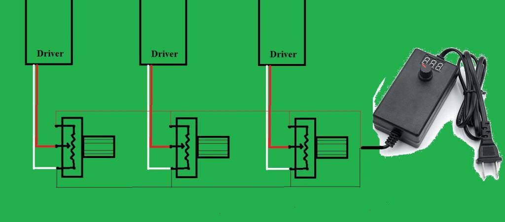
And that was it. It turns my lights up and down, and the displays resolution gives me repeat adjustment to within 1%. So the space is exactly how I found it, when I turn them back up to leave.
Each light still retains the individual adjustment, allowing some balancing.
There was an unexpected error, when they were used in a different manner. If my psu was set to put just 3v across the resistor, the meanwells own 10v output could start to figure into things. I could turn one up from nothing, increasing brightness due to the internal 10v, but then continued twisting of the resistor took it to the external 3v. The effect was that the light could get brighter as you turned the resistor to number 8, but from 8 to 10 it dimmed a little again.
In use, you set the external psu to 10v or more for full brightness, with the Variable resistors also on full. Then run around turning down the ones that are too bright, balancing your light. Then the whole lot goes up and down nicely using the PSU. Sorted.
You may find this isn't for you, and that your ballast can be dimmed by modifying the AC input with a more typical dimmer. But hay.. It's a choice.
Edit: I wouldn't use an AC side dimmer myself. The driver is regulating with rapid switching, and the dimmer is doing the same, turning the driver on/off rapidly. The driver must get this quick pulse of power, stabilise, and then get it's own chopping done, before the dimmer cycles back off. This can be literally impossible, and is very much luck. There is real room for error that causes aging or worse. As an example, I have a ups and a temperature sensing fan speed controller. I can't use them together. The extractor spins slow, and makes a high pitched squeal. My fan motor becomes a speaker..
Enter the drawing
And that was it. It turns my lights up and down, and the displays resolution gives me repeat adjustment to within 1%. So the space is exactly how I found it, when I turn them back up to leave.
Each light still retains the individual adjustment, allowing some balancing.
There was an unexpected error, when they were used in a different manner. If my psu was set to put just 3v across the resistor, the meanwells own 10v output could start to figure into things. I could turn one up from nothing, increasing brightness due to the internal 10v, but then continued twisting of the resistor took it to the external 3v. The effect was that the light could get brighter as you turned the resistor to number 8, but from 8 to 10 it dimmed a little again.
In use, you set the external psu to 10v or more for full brightness, with the Variable resistors also on full. Then run around turning down the ones that are too bright, balancing your light. Then the whole lot goes up and down nicely using the PSU. Sorted.
You may find this isn't for you, and that your ballast can be dimmed by modifying the AC input with a more typical dimmer. But hay.. It's a choice.
Edit: I wouldn't use an AC side dimmer myself. The driver is regulating with rapid switching, and the dimmer is doing the same, turning the driver on/off rapidly. The driver must get this quick pulse of power, stabilise, and then get it's own chopping done, before the dimmer cycles back off. This can be literally impossible, and is very much luck. There is real room for error that causes aging or worse. As an example, I have a ups and a temperature sensing fan speed controller. I can't use them together. The extractor spins slow, and makes a high pitched squeal. My fan motor becomes a speaker..
Last edited:


