What's new
  • Happy Birthday ICMag! Been 20 years since Gypsy Nirvana created the forum! We are celebrating with a 4/20 Giveaway and by launching a new Patreon tier called "420club". You can read more here.
  • Important notice: ICMag's T.O.U. has been updated. Please review it here. For your convenience, it is also available in the main forum menu, under 'Quick Links"!

Ogre's DIY Ebb & Grow / Multi-Flow Controller Tutorial

OgreSeeker

Active member
Ok, I have to make a disclaimer like everyone else.
***I did not invent this unit. My unit is an improved, copycat version***
***Follow these directions step by step and this unit is foolproof***

In the spirit of Blaze, Krypto, SoQuick, HOG, MiaStoner, Bubbleman and all you other cats out there that have inspired me throughout the years...

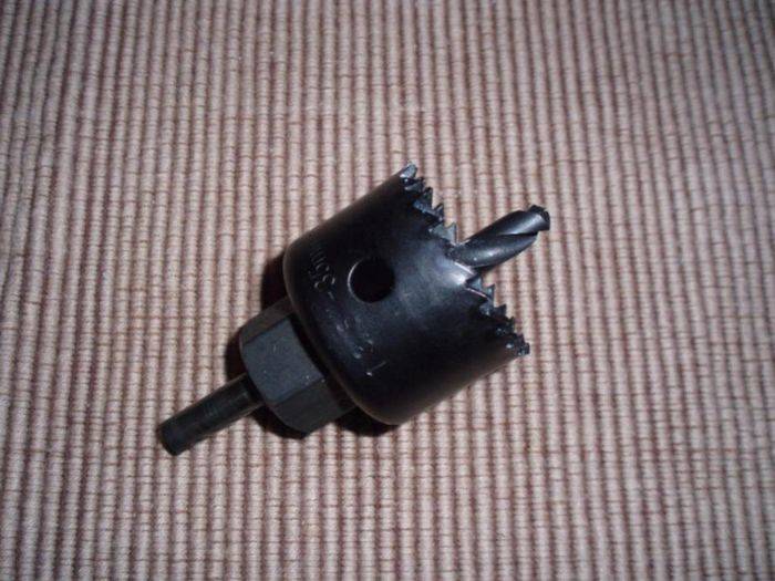
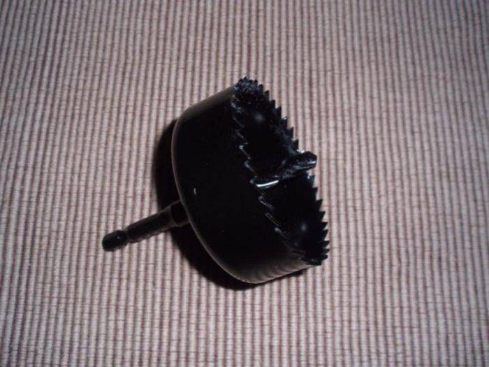
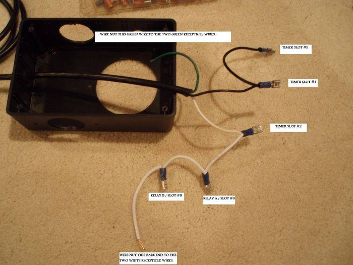
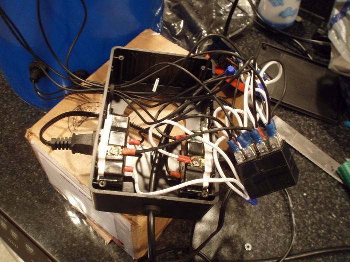
I've built a multi-flow controller and will be putting together pics and information (parts list, item numbers, how to, etc) and documenting it here. This will -hopefully- be an easy to follow, easy to understand tutorial. Should be easy as 1-2-3 -IF YOU PAY ATTENTION-:pimp3:

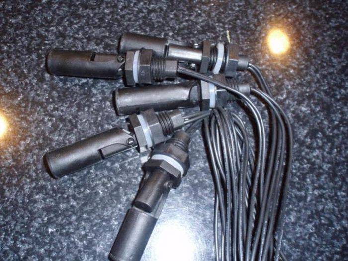
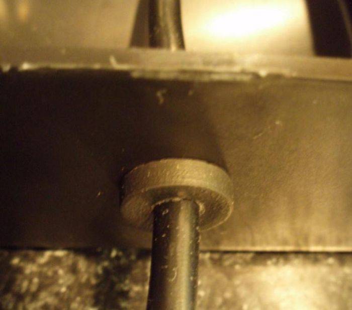
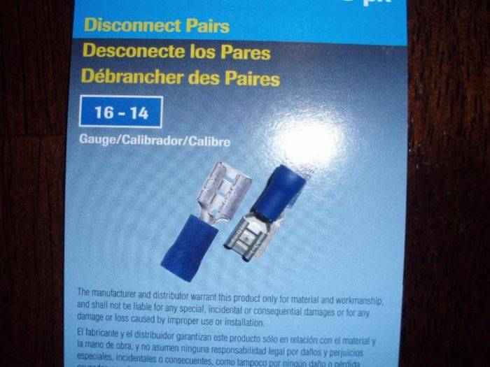
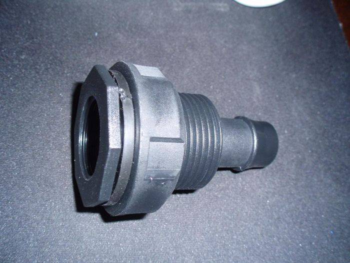
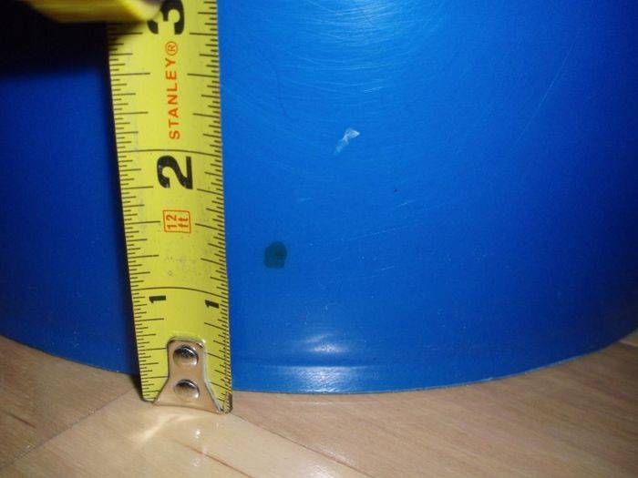
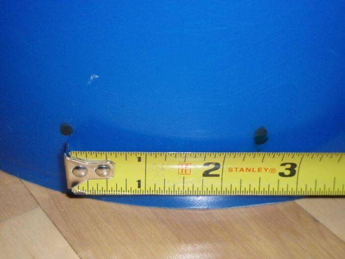
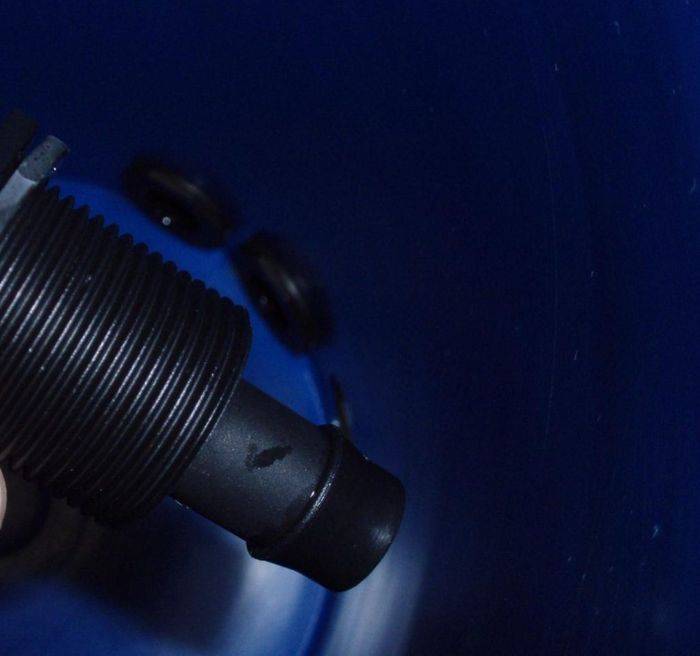
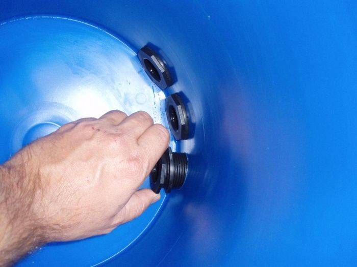
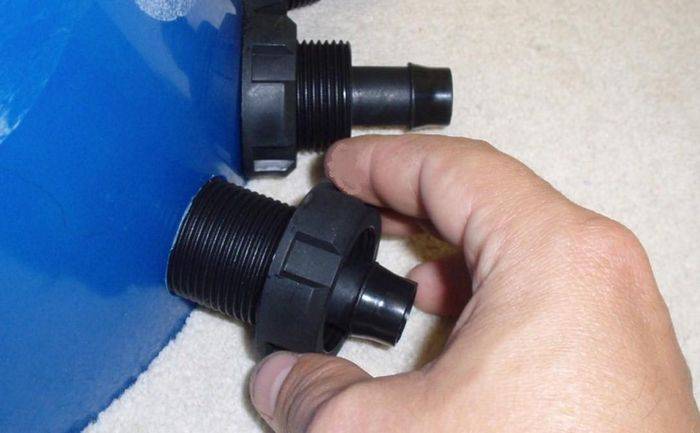
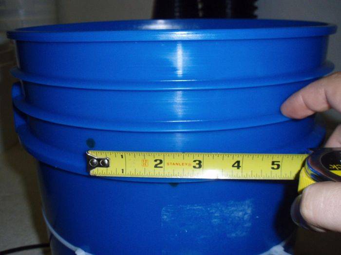
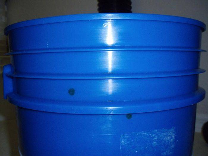
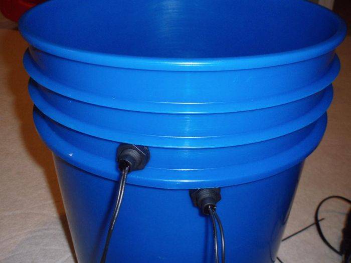
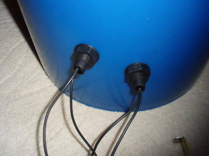
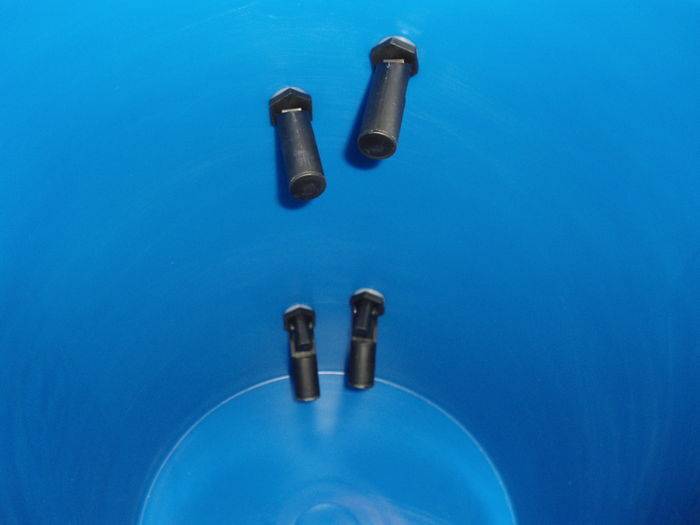
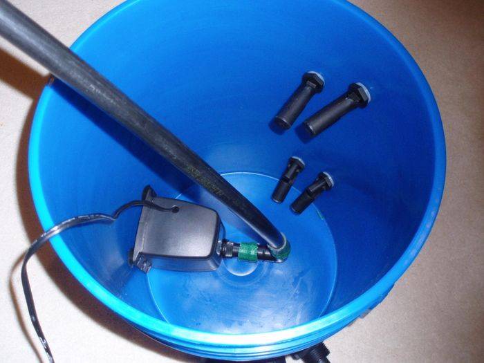
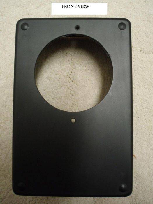
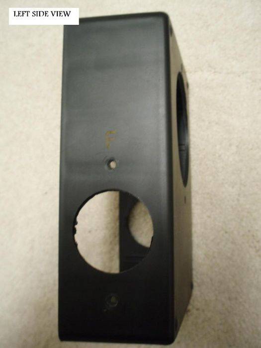
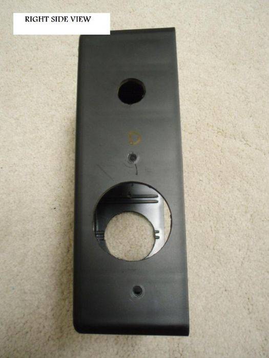
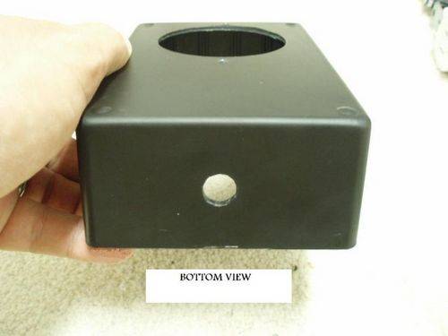
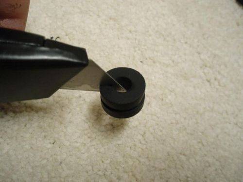
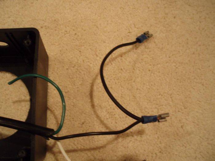
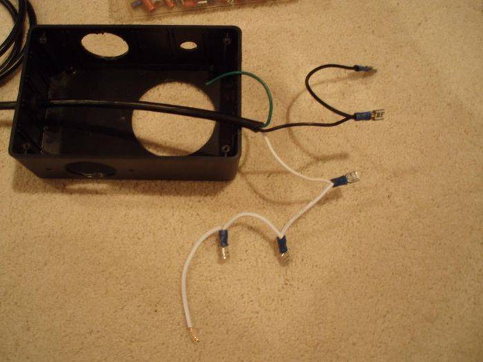
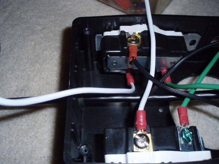
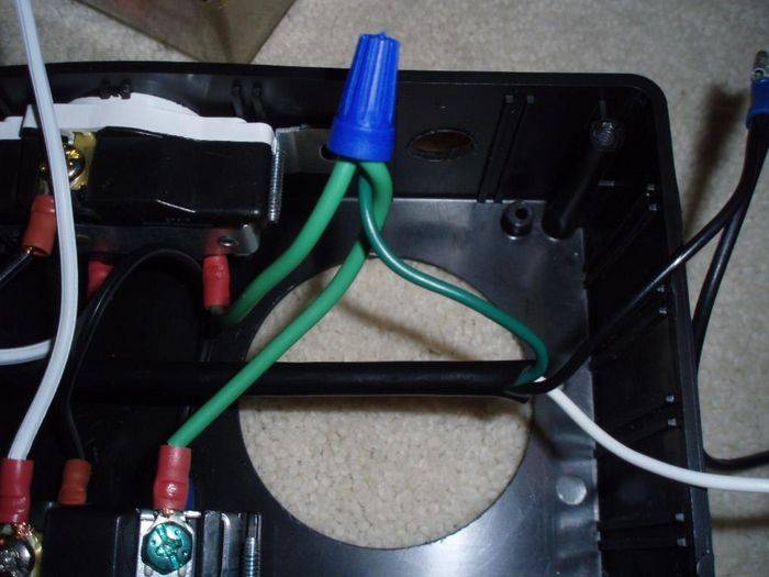
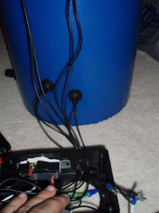
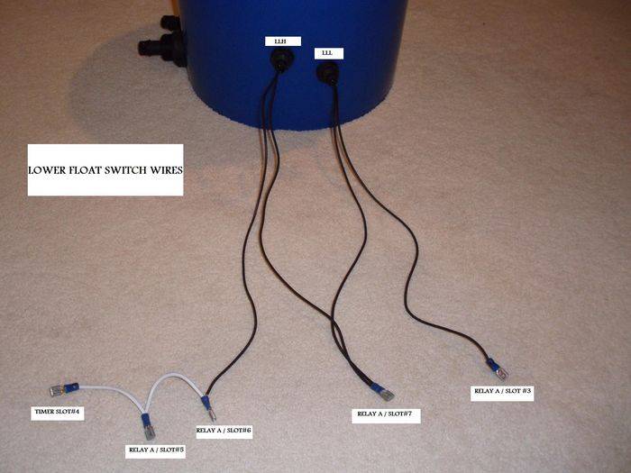
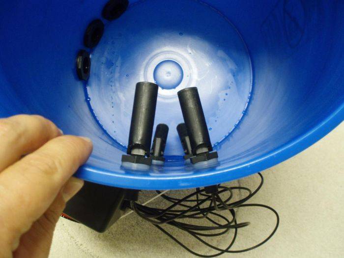
I'll start by saying there is a small but significant difference in my controller VS the other DIY controllers. I use horizontal floats instead of vertical floats. This eliminates the need to use grommets,elbows, glue etc when installing the float switches. Instead all you have to do is drill the hole, feed the wire through and tighten the nut on the opposite side (just like a bulkhead fitting). :muahaha:
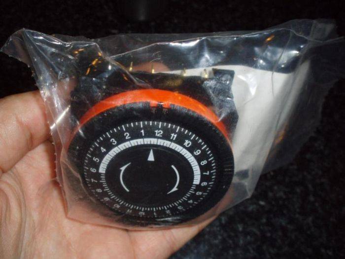
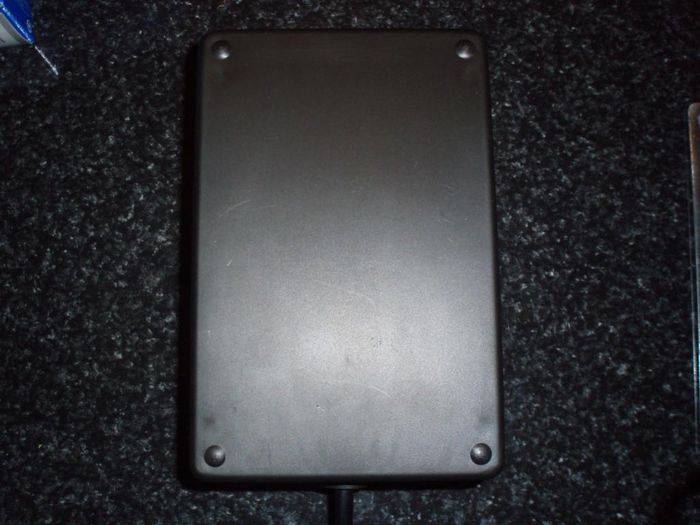
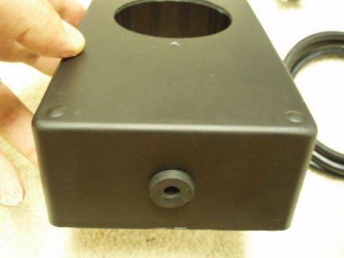
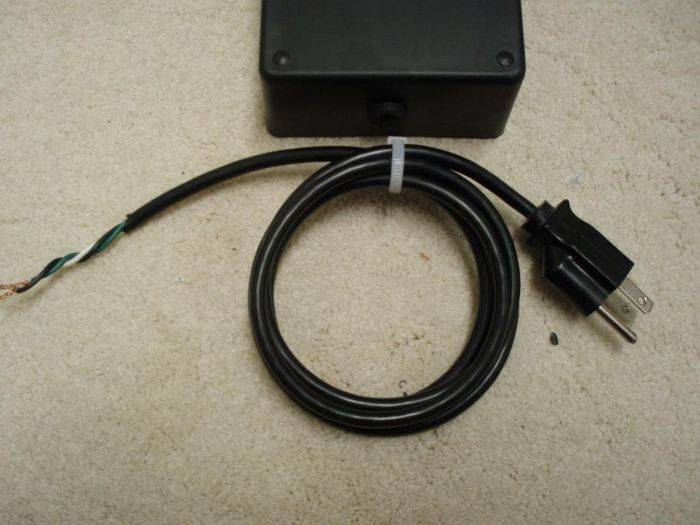
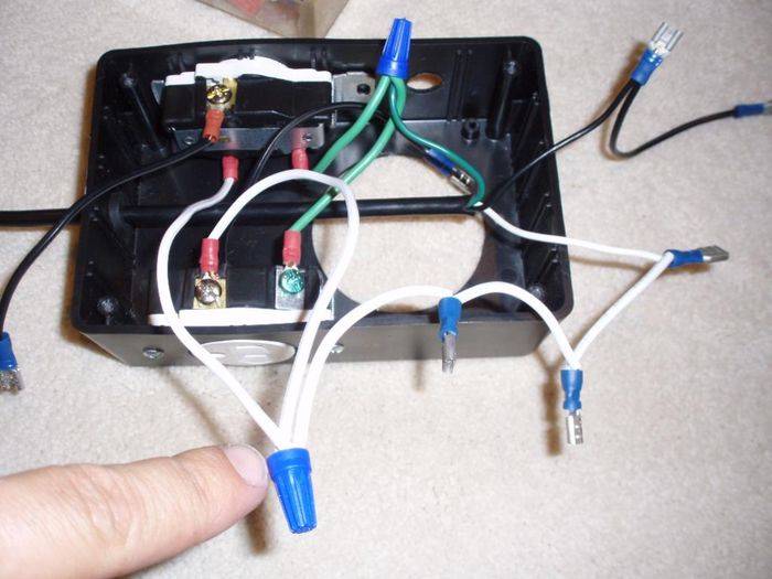
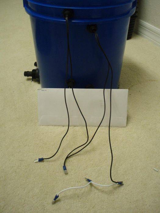
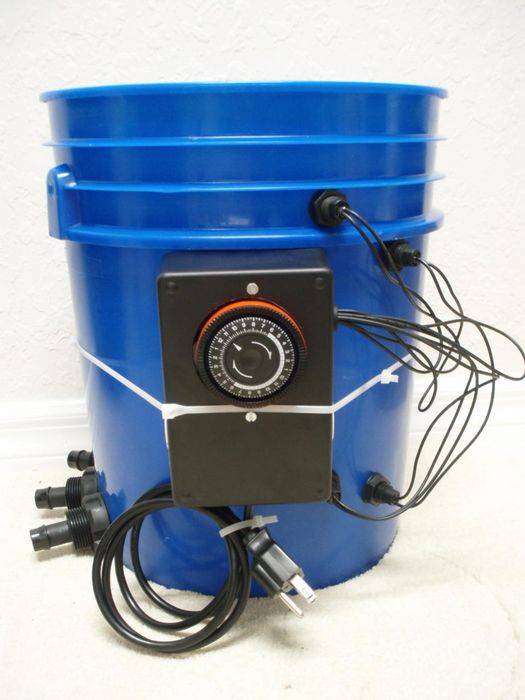
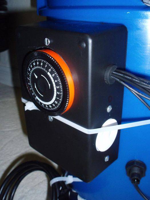
Here are a couple pics of the finished controller.
I'll start getting my stuff together and get back at ya guys with an update soon...​


Please don't be intimidated by the length of this thread. If you actually read the thread then you will see that this unit is extremely easy to build. If you just scroll through the pictures without reading it's going to look overwhelming and your gonna say to yourself "holy sh*t...I ain't doing all that".

This controller cost me around $120.00 to build.


Last edited:

OgreSeeker

Active member
Update:
June-22-2008


THANKS Pontiac!!!


OK HERE WE GO...

Good day everyone. Today I will start with a complete parts and tools list.


Parts List


- x1 SPDT FIVE Terminal Timer / Time Clock, 24Hr, 120V
(Part Number: TA4079)
One place to get it is:

CLICK HERE...this is the timer you need
-OR-
***HERE***
-OR-
***HERE***


- x4 Horizontal float switches
One place to get them:
***HERE***

(Part Number: FLT231)
-OR-
***HERE***
OR
***HERE***


- x2 125VAC/10A DPDT Plug-In Relay. You can get these from Radio Shack (Part Number: 275-217) ***Click Here***


- x1 6' or 8' three prong power cord (at least 18/3 AWG). These are common and easy to find. Hell, you could even cut an old computer power cord (that's what I did).


- x2 small grommets from the electrical section of Home Depot or Lowes. These will be used on the controller box for wiring. One grommet for your power cord and one for your float switch wires. Be sure that the grommets you get are large enough for the cord to fit through but small enough to be snugg. The size of your grommet depends on your cord circumference.


- x1 roll of 18 awg cord at least 15' to 20' (never hurts to have extra). You can get this at hardware stores, auto parts stores or wally world (mine came from wal-mart as a 15' lamp replacement cord.


- x2 15amp 120v standard single outlets. You know where to get these :bashhead:


- x2 Small nuts and bolts to secure the timer inside the controller box. Make sure the bolts are small enough to fit the timer bolt holes.


- x6 Spade terminals (these are to be used on the single outlets and are not necessary. You can just wrap the stripped wire around the screw and tighten but I prefer to use spade terminals). Get these at Home Depot, Lowes or auto parts store.


- x17 blue or red disconnects (get plenty of extras just in case you screw up). I used what I had on hand so mine are mix and match, red and blue. You can get these at Home Depot, Lowes or auto parts store.
TIP:Be sure that your crimp is tight and the wire doesn't slip out of the disconnect easily.


- x3 small wire nuts -OR- you can be extra cheap and use electrical tape.


- x1 Project box / enclosure. The one I used is 6"x4"x2" (radio shack part number 270-1806) but It was a tight fit. It might be a good idea to use a larger box (Radio Shack part number 270-1807)
***Smaller Box Here***
***Larger Box Here***


- x2 Pumps (one for controller and one for main reservoir). I won't be explaining construction of the complete system in this tutorial, only the controller.
Pump size depends on how large your system will be and how large your fill/drain lines are. Anything from a 300gph to 600gph will work fine.
TIP: 3/4" line will significantly speed up fill and drain times. 1/2" just doesn't cut it.


- x4 3/4"bulkhead fittings (Worms Way Part Number BBH202). If you plan on using 1/2" line the go with Worms Way part number BBH201. The number of bulkheads needed depends upon the size of your system. More planter buckets mean more holes/bulkheads need to be added to the controller so as to run more lines.
TIP: 3/4" line will significantly speed up fill and drain times. 1/2" just doesn't cut it.
***3/4" Bulkheads Here***
***1/2" Bulkheads Here***


- x2 90° barbs inserts. These will be popped into the the pump lines to prevent siphoning. One gets popped into the pump line in the controller and one gets popped into the other pump line in the reservoir. (pics coming soon of actual install)


- x1 Bucket. A 5 gallon bucket is typically used in this application (mine is blue).
Tip: Controller bucket should be a little larger than your planter buckets. Again, I won't be explaining construction of the complete system in this tutorial, only the controller.


Tool List

- Wire crimping pliers (any hardware store has these for $5 to $15)


- 5/8" spade bit (FOR DRILLING FLOAT SWITCH HOLES)


- 1 3/8" Hole saw. (FOR DRILLING RECEPTICLE AND BULKHEAD HOLES)


- 2 1/2" Hole Saw (FOR DRILLING TIMER HOLE)


- Razor Blade knife and/or knife (DO YOU REALLY NEED A PICTURE??)


- Phillips and straight head screwdriver (DO YOU REALLY NEED A PICTURE??)


I think that about does it for the parts and tools list. I will edit this section later if I forgot anything.
Until next time friends...
 
Last edited:

OgreSeeker

Active member
plumpm0nkey,
I'm a big fan of DWC. The reason I went with this system over DWC is because I didn't have the extra money for lids/net pots, air pumps and chiller. I already had just about everything I needed to make the multi-flow except the controller (which cost me around $100.00 to build).
I will be adding details about my particular system (amount of buckets, size of buckets) as the tutorial moves forward. I will be running between 40 and 70 buckets at any given time so I'll probably build two controllers and split the system in two.
Only thing I need to purchase now is a shit load of hydroton.


Budweiser13,
Thanks man...it's coming along!
 
Last edited:

OgreSeeker

Active member
I looked into that system and found that they've yet to figure out a way to incorporate one timer. They use two timers to control that unit.
My total cost was about the same as the aquahub unit.
 

plumpm0nkey

Member
wtf they have 2 timers huh, yeah i know that you know what your doin. in the begining when your babies dont have enough roots to dangle down to the water level i used lantern wicks to draw up the water in the hydrotron. what you got goin on strain wise?
 

OgreSeeker

Active member
Update:
June-24-2008


STEP#1 - PREPARE CONTROLLER BUCKET BY DRILLING HOLES

We'll start by measuring and drilling our fill and drain holes in the bottom side of the controller bucket. These holes are where you will be installing the bulkheads for your fill / drain lines that run to your buckets.
How many holes you drill will depend upon the size of system your building and how many lines you'll need.
Start by measuring at least 1 1/4" up from the bottom of your bucket. Mark a spot for hole#1.


Measure 2 1/2" over from hole #1 and mark your spot for hole #2. Repeat this process if you need more fill / drain lines (I will be using 3 holes in my setup).
Again, the number of lines / holes needed depends on how many buckets you want to run (more buckets = more lines needed).


Using your 1 3/8" hole saw, drill out your fill/drain holes. Once you've cut your
holes you can install the bulkheads. Just slide the bulkhead through the bucket from the inside and tighten the plastic nut on the outside like so...


Next we will be measuring and drilling our holes for the lower float switches. Position your bucket in front of you so the bottom holes you just drilled are facing out to your left. The side of the bucket that is now facing you is where your float switches will be located.
I'll throw in this pic for reference. This should give you a better understanding of where the float switches should be in relation to the fill/drain holes.


Measure 3" from the bottom of your bucket. Mark your hole. This hole will be for your "Low Level Low" or "LLL" float switch.


Now measure 2 1/2" over and 1/2" up from the LLL hole. Mark your hole. This hole will be for your "Low Level High" or "LLH" float switch.


Now lets talk a little about the upper float switches. The height at which the upper floats are installed is determined by how tall your
planter buckets are. You'll need to measure the height of your holding bucket (the bucket that your hydroton filled bucket slides in to). This is what I use...


The upper floats will be installed in the controller so that the "High Level High" or "HLH" float is 3/4" lower than the height of your planter holding bucket.
For example, the buckets I use in my system are exactly 12" tall...


so my "HLH" hole should be drilled about 11 1/4" high on the controller bucket. Get it?


TIP: If you know that your grow area is not level in some areas, you may want to position the "HLH" float even lower in the controller (maybe 1" lower rather than 3/4").

Once you have the "HLH" hole marked, measure 2 1/2" over and 1/2" down from the "HLH" hole.


Mark your hole. This is where your "High Level Low" or "HLL" float switch will be installed.

Now that all of your float switch holes are marked, use the 5/8" drill bit to drill your holes.


Feed your float switch wires through the holes and tighten the nut on the outside.


VIOLA...leak free and you didn't have to use grommets and elbow & all that shit.

Look closely at this picture. Your floats should be in this position after installation.


You may have noticed that I didn't drill any holes for the pump lines. That's because it's easier to lay the pump suction side down, add an elbow and come straight out the top of the bucket rather than drilling holes and installing grommets. You remember what your momma told ya....KISS!


It's time to take a break. Go burn one (I'll be joining ya) and when we get back we'll do a lil prep work on the 120v outlets and project box...
 
Last edited:

OgreSeeker

Active member


STEP#2 PREPARE CONTROLLER BOX BY DRILLING HOLES, MODIFY RECEPTACLES AND LABEL THE RELAYS


OK,
Let's get back to it. We're going to modify the 120v receptacle to fit into our project box (skip this step if you decided to purchase the larger box and have ample room).
I'm using the small project box. To get these receptacle to fit we need to cut the bottom metal bracket off. I used a dremmel tool. you can use whatever you have on hand.


Now set these aside for later.


We're gonna prep our relays now. This is pretty simple. Take your two relays and mark one "A" and the other "B". You can tape them together for easier handling if you wish (that's what I did).


Put those aside for later.


We will now prep the project box by drilling our holes.

-Project box front: Measure 2" from top of the project box and mark it (be sure to center it). Use your 2 1/2" hole saw to drill this timer hole.


-Project box left side view: Measure 2" up from the bottom of the box and mark it being sure to try and center your mark. Use your 1 3/8" hole saw to drill this receptacle hole. ***This is the "FILL" side receptacle hole- mark it with an "F"***


-Project box right side view: Measure 2" up from the bottom of the box and mark it being sure to try and center your mark. Again, use your 1 3/8" hole saw to drill this receptacle hole. Now measure 2 1/2" up from the receptacle hole and mark your spot for a grommet hole. Grommet will be installed in this hole for your float switch wires. The size of this hole is determined by the size of grommet you can obtain. My grommet holes are 5/8"...yours may be larger or smaller - doesn't really matter-. ***This is the "DRAIN" side receptacle hole- mark it with a "D"***


-Project box bottom view: Drill another grommet home for the power cord. Again, the size of this hole is up to you and the size of your cord.

411630049-med.JPG


***IMPORTANT***
Before drilling any holes in the project box it is important that you position the timer and receptacles inside the box, mark the screw holes and make sure everything will fit correctly - DO A TEST FIT -. It will be tight if using the small box but it will fit. This is why I would go with a larger project box if I did it over again.


Install the bottom "power cord" grommet then slide your power cord through. Be sure to leave enough slack wire to work with.
TIP:Grommets are much easier to install if they are sliced on one side.

411630050-med.JPG


4116300511-med.JPG


Last edited:

OgreSeeker

Active member


STEP#3 - PREPEARE AND INSTALL RECEPTACLE WIRING AND POWER CORD

I think we're about ready to start wiring this bad bay...

Let's start prepping the receptacles.
***Keep in mind that when I mention "green wires", "white wire" or "black wires" this is for reference only. Your wires can be any color but it's less confusing to use the correct colored wires***


Cut two small pieces of green wire about 4" to 5" long and strip the ends. Crimp one spade terminal to each green wire. Now connect those green ground wires to the green screw on the receptacles.


411630056.JPG


Cut two small pieces of white wire about 4" to 5" long and strip the ends. Crimp one spade terminal to each white wire. Now connect those white wires to the silver colored screw on the receptacles.


411630061.JPG


Cut two small pieces of black wire about 4" to 5" long and strip the ends. Crimp one spade terminal to each black wire. One the other end of the black wires, crimp one disconnect.


Your black wires should look like this...


Now connect those black wires to the brass colored screw on the receptacles.
Your receptacles should now look like this...


We have the receptacles prepped so let's set those aside and wire the power cord.

Strip the end of the ***white*** power cord wire and crimp three disconnects leaving the end wire bare as seen in the photo below.


Strip the end of the ***black*** power cord wire and crimp two disconnects. It should look like this.


Your project box should look like this...


Install the receptacles into the project box. Now you see why we had to cut the bottom off of these receptacles.


Here's where we should be at this point.


Connect the two green receptacle wires to the green power cord wire with a wire nut.


Connect the two white receptacle wires to the bare end of the white power cord wire with a wire nut.


Now set the prepped controller box aside...we's abouts to starts some bucket wiring!!​


OK guys...it's time for me to call it a night (what's left of it). The wife just came out and asked me what the f*ck I was still doing up.
Until next time...
 
Last edited:

OgreSeeker

Active member
UPDATE
JUNE-25-2008


STEP#4 - WIRING THE BUCKETS AND CONTROLLER


All we have left to do is wire our floats, hook all of our prepped wires to the timer and relay, cram it all into the project box
and we're done! Let's get to it...

We'll start by wiring our lower floats.
1. Take one of the "Low Level High" wires and crimp three disconnects to it.
2. Take the other "Low Level High" wire and one "Low Level Low" wire and connect them together with one disconnect.
3. Take the remaining "Low Level Low" wire and crimp one disconnect to it.

The lower floats are finished.
***YOUR LOWER FLOAT WIRES SHOULD LOOK EXACTLY LIKE THIS PICTURE***


Now for the upper floats...
1. Take one of the "High Level High" wires and crimp one disconnect to it.
2. Take the other "High Level High" wire and one "High Level Low" wire and connect them together with one disconnect.
3. Take the remaining "High Level Low" wire and crimp three disconnect to it.

***YOUR UPPER FLOAT WIRES SHOULD LOOK EXACTLY LIKE THIS PICTURE***


All of your floats, receptacles and power cords are now prepped/wired and ready to be hooked up to the relays and timer.


WOOOOOOOOOOHOOOOOOOOOO we're almost there!!!!!
Is it time for a bong hit? I think so :


It's time to hook it all together!

***IT IS VERY IMPORTANT THAT YOU FOLLOW THESE STEPS VERY CAREFULLY. YOU HOOK IT UP WRONG...IT AIN'T GONNA WORK SO PAY ATTENTION******

First, take all of your float switch wires and feed them through the grommet hole in the side of your controller box.


Slice the grommet and put it around the wires. Now work the grommet into the hole. If it's tight just use a straight
screwdriver to force the grommet into place.

***TIP: Before you feed the float wires into the project box you may want to label your wires. Once you feed the wires through the grommet hole it is very hard to keep track of what's what unless they are marked/labeled. If you scroll down there are some pictures for reference. Use these pics to label your wires then feed them through.***

Now here's how it all gets wired...

I'll show you with pics rather than try to explain it.
(WIRE AS SHOWN)

POWER CORD WIRES:
**Green wire and white "bare end" wire should already be connected***
(From top to bottom)
TIMER SLOT#5 / TIMER SLOT#1 / TIMER SLOT#2 / RELAY A SLOT#8 / RELAY B SLOT#8


LOWER FLOAT SWITCH WIRES:
(Left to right)
TIMER SLOT#4. / RELAY A SLOT#5 / RELAY A SLOT#6 / RELAY A SLOT#7 / RELAY A SLOT#3


UPPER FLOAT SWITCH WIRES:
(lEFT TO RIGHT)
RELAY B SLOT#3 / RELAY B SLOT#7 / TIMER SLOT#3 / RELAY B SLOT#5 / RELAY B SLOT#6


Now you need to connect the two black receptacle wires to the relay.
Remember I told you earlier to mark one receptacle "F" for fill and the other "D" for drain?

1.Take the black wire from the "Fill" receptacle and connect it to RELAY B SPOT#4
2.Take the black wire from the "Drain" receptacle and connect it to RELAY A SPOT#4


The wiring is complete.
This is what it should kinda look like.


411630082.JPG


Now cram the timer, relays and all that mess into the project box.


Use your small bolts and nuts
to secure the timer in place. Screw the back plastic cover onto the controller box. Secure the completed controller box to the
bucket with one large plastic cable tie (make sure it's tight).


WE'RE FINISHED!!!!


Do a test run on the unit. I didn't feel like hooking up the complete system up just to do a test run. Here's how you can do a quick test to
be sure it's working without doing a complete hookup.
Plug one standard room lamp into the fill receptacle.
Plug one standard room lamp into the drain receptacle.
You can mimic the fill/drain process by manually raising and lowering the floats with your hand. Your lamps will come on and off accordingly mimicing the pumps.


TROUBLESHOOTING

If for some reason your controller doesn't seem to be working correctly the first thing you'll want to do is switch outlets that your pumps are plugged into. This will more than likely fix you problem. If not, come back here and ask questions.
If you follow this tutorial step by step there won't be any problems.


If this tutorial helps just one person then I've done my job.
 
Last edited:

OgreSeeker

Active member
Hey plump...
Your setup is sweet as hell. That is one of the cleanest, well prepared system I've seen in a while!
Here's the strains I'll be working with...

Serious Seeds - AK-47 & Bubblegum
Reservoir - Double Strawberry Diesel

I've got a few more but I don't want to run to many different strains at one time.
 
Last edited:

smoke1sun

What Goes Around Comes Around. But Am I Comming Or
Veteran
A little out of my league, but this is a great detailed tutorial. Thanks k++++++
 
Nice! I built the Krypto controller a few years ago but didn't have much luck with it...I'm sure its something I did wrong.
Something came up recently about the system I hadn't thought of and might be the root of my problem, my pumps were kinda big and someone thought they filled my controller bucket too fast. you see my issue was it would fill and shut off, fill and shut off very quickly and that made the floats bounce up and down too much.
Am I making any sense? What I'm saying it didn't work smoothly it was very eradic and hard to control.
My pump size was a 225 gph i think, do you have any thoughts on this?
great job on the controller! thanks!
 

OgreSeeker

Active member
It is normal for the pumps to kick on and off during the fill a dn drain cycle (about every 15 to 45 seconds until all buckets are evenly filled is normal - depends on how quickly your controller fills the planters and how large your lines are). It is not normal for the pump to kick on and off QUICKLY. How often did it kick on?
I do understand what your saying though.
I don't think it's the size of your pump cause I'm using 300GPH pumps. Sounds to me like your floats didn't have enough space between them to create a hysteresis or the floats are not connected correctly to the relay but I can't be sure without actually seeing it.
- I very well could be wrong-.


"HIGH LEVEL HIGH FLOAT"

hysteresis

"HIGH LEVEL LOW FLOAT"


"LOW LEVEL HIGH FLOAT"

hysteresis

"LOW LEVEL LOW FLOAT"


The space in between the floats creating a hysteresis is what should be keeping you pumps from kicking on and off to quickly. -does that make sense-??
 
Last edited:

SumDumGuy

"easy growing type"
Veteran
Slosh effect...

Slosh effect...

Hi OgreSeeker... Nice clean-cut revision of the controller. I had already ordered my parts based on Krypto's thread before I ran into yours... So I bought the i-Float switches from aquahub which'll require the 90 degree elbow... Though I bow to Krypto for initially introducing me to this device - I thankyou for making the wiring tutorial very easy to understand. Both you guys are certainly masters of your trade.

As for the additional floats LLH and HLL - Why not just use only two floats LLL and HLH - Is it because of sloshing? I'm studying up on relays and Reed switches so I'll be there soon on the technical side but wondered about this for some time...

I've yet to make a grow album on IC but will do it on my next grow incorporating this system. The only thing I'm waiting for are the pumps. I ordered the MaxiJet 900's and I already purchased the 1/2" ID tubing for nine 2 gallon buckets. Do you also think I'll be okay with this? Again thankyou for all of this information. I feel like these buckets are really strong and much sturdier by using bulk-head fittings. My system should be up by Tuesday as the pumps arrive on Monday.

I have an OG seedling 2 weeks old in veg - Tossing in all my eggs in hopes it's a female. This is the last of 3 seeds I received from a friend and the first two turned out female but I never cloned :-(

Here's my album from WeedFarmer
 
Last edited:

SumDumGuy

"easy growing type"
Veteran
hysteresis

hysteresis

OgreSeeker... You are the MAN!!! Thankyou for informing me on "hysteresis" it's been a while since I've been in class so I found this on Wikipedia. I feel like I have a much firmer understanding on this... Contact bounce was listed under the "Schmitt trigger". It sorta makes sense...

Electronics

Sharp hysteresis loop of a Schmitt trigger. Hysteresis can be used to filter signals so that the output reacts slowly by taking recent history into account. For example, a thermostat controlling a heater may turn the heater on when the temperature drops below A degrees, but not turn it off until the temperature rises above B degrees. Thus the on/off output of the thermostat to the heater when the temperature is between A and B depends on the history of the temperature. This prevents rapid switching on and off as the temperature drifts around the set point.

A Schmitt trigger is a simple electronic circuit that also exhibits this property. Often, some amount of hysteresis is intentionally added to an electronic circuit (or digital algorithm) to prevent unwanted rapid switching. This and similar techniques are used to compensate for contact bounce in switches, or noise in an electrical signal.

A latching relay uses a solenoid to actuate a ratcheting motion that keeps the relay closed even if power to the relay is terminated.

Hysterisis is essential to the workings of the memristor, a circuit component which "remembers" changes in the current passing through it by changing its resistance.

Contact bounce
Contact bounce (also called chatter) is a common problem with mechanical switches and relays. Switch and relay contacts are usually made of springy metals that are forced into contact by an actuator. When the contacts strike together, their momentum and elasticity act together to cause bounce. The result is a rapidly pulsed electrical current instead of a clean transition from zero to full current. The waveform is then further modified by the parasitic inductances and capacitances in the switch and wiring, resulting in a series of damped sinusoidal oscillations. This effect is usually unnoticeable in AC mains circuits, where the bounce happens too quickly to affect most equipment, but causes problems in some analogue and logic circuits that respond fast enough to misinterpret the on-off pulses as a data stream.

Sequential digital logic circuits are particularly vulnerable to contact bounce. The voltage waveform produced by switch bounce usually violates the amplitude and timing specifications of the logic circuit. The result is that the circuit may fail, due to problems such as metastability, race conditions, runt pulses and glitches.

There are a number of techniques for debouncing (mitigating the effects of switch bounce). They can be split into wet contacts, timing based techniques and Hysteresis based techniques.
 
Last edited:
Top