
-
Happy Birthday ICMag! Been 20 years since Gypsy Nirvana created the forum! We are celebrating with a 4/20 Giveaway and by launching a new Patreon tier called "420club". You can read more here.
-
Important notice: ICMag's T.O.U. has been updated. Please review it here. For your convenience, it is also available in the main forum menu, under 'Quick Links"!
You are using an out of date browser. It may not display this or other websites correctly.
You should upgrade or use an alternative browser.
You should upgrade or use an alternative browser.
My DIY LED grow light
- Thread starter vukman
- Start date

Hi all.......just jumped in before I start my day with the doctor meetings and all that shit...
Hemp..thank you brother...series it is.. The white light are pushing the 'big' driver to it's limit with 30 chips @ 3.4V..") .........series it is..
.........series it is..
Petflora..Heya...I've been lurking in that 'other' forum so I've been watching what you and sailorman say..,,,,thank you for your words my friend...it's very appreciated..
Hemp..thank you brother...series it is.. The white light are pushing the 'big' driver to it's limit with 30 chips @ 3.4V..
.........series it is..Petflora..Heya...I've been lurking in that 'other' forum so I've been watching what you and sailorman say..
,,,,thank you for your words my friend...it's very appreciated..Looking good. I would attempt something similar, but I don't remember a damn thing about electrical wiring (I learned all this stuff in physics II, but there are a few years and a lot of bowls smoked between then and now). In any case. Do you have a full list of the LEDs you're using and an idea of what to total at-the-wall wattage will be?
Hi everyone...please excuse the delay in this posting but my fucking knee is killing me for some reason.. I'm actually having problems sitting, standing, laying down..etc..etc.. Even the weed is having a problem cutting through the pain this time around. Have no idea what the hell I did but............whatever.. that's life with this body...
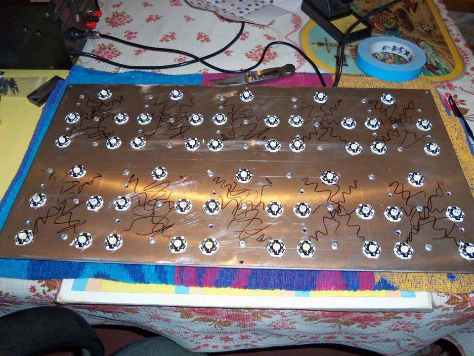
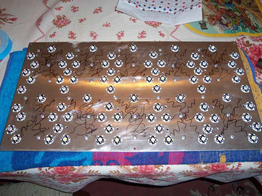
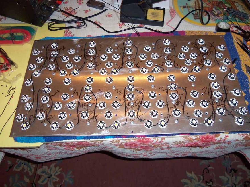
I've managed to prep to blues and the 630 reds. Soldering those damn little contacts is a fucking pain in the ass but it has to be done. Another thing is the smell of the rosin is bothering me as well...hold shit....I sound like I'm on the fucking rag or something!!!!!!! LOL....no offence ladies..
Anyway, here are the pictures of what's been done. As you can see, the prep work it almost done. Connecting the wires should be easy enough and I am getting more adept at the soldering anyway so........well........it is what it is.
I'll answer questions tomorrow if that's okay with everyone, I gotta go ice the knee..
Thanks for following as always..
If you can solder the connections before gluing the stars down, it is way easier. The damn heat sink really works against you when you are trying to solder.
I don't recall if we've ever discussed topical oil - if you haven't tried it, you may find it to be very beneficial for your knee. If I had known about it years ago, it might have been enough to keep me away from needing opiates. The stuff is miraculous. The only person that I've seen that it hasn't helped is a 99-year old man (literally!) with bad knees, and I'm not convinced that he actually tried it after I told him what was in it.
I don't recall if we've ever discussed topical oil - if you haven't tried it, you may find it to be very beneficial for your knee. If I had known about it years ago, it might have been enough to keep me away from needing opiates. The stuff is miraculous. The only person that I've seen that it hasn't helped is a 99-year old man (literally!) with bad knees, and I'm not convinced that he actually tried it after I told him what was in it.
Before soldering the wires to the PCB stars I put a small droplet of solder on the contacts and melted with a 40W soldering iron with copper tip (I really like copper tips more than any other type because is more easy to hold melted solder that way).
The most annoying part was the cutting of the wires to the corresponding length and removing the PVC coating from both ends. It's a process that never seems to end.
Pay much attention to the polarity : the negativ (-) output from one led connects to the positive (+) input of the following led. But keep in mind that some leds are protected to reverse current, having a diode connected in parallel , but with reverse polarity, so if you mount the led in the wrong way, the other leds will still lit.
I've put in 4 switches already so yes, the light will be for veg and flower.
Hemp......brother.....I've already soldered the contacts......that is what is taking so long..heheh....the ones you see on the heatsink are already taped on.. now it's just a matter of attaching the wires...yes...heat the wire until it grabs the solder on the contact and I'm done..........theoretically anyway..
Also, if you zoom in, you can see that all of the chips are facing the same way to soldering them will be easier when it comes to making sure the polarity is right.....Always thinking brother...always thinking..hheheheh...I also agree about skinning the wires...UGH......since I'm useing 22awg, I might just skin then with my teeth!! LOL...I used to to that with 14awg but it gets a little tough..
As for the rest of the questions which I seen especially pertaining to the LEDs..numbers, size, wave lengths, ratios, wattage draw..........all that will be answered after the build and testing...
thank you all as always.........
Hemp......brother.....I've already soldered the contacts...
...that is what is taking so long..heheh....the ones you see on the heatsink are already taped on.. now it's just a matter of attaching the wires...yes...heat the wire until it grabs the solder on the contact and I'm done..........theoretically anyway..Also, if you zoom in, you can see that all of the chips are facing the same way to soldering them will be easier when it comes to making sure the polarity is right.....Always thinking brother...always thinking..hheheheh...I also agree about skinning the wires...UGH......since I'm useing 22awg, I might just skin then with my teeth!! LOL...I used to to that with 14awg but it gets a little tough..
As for the rest of the questions which I seen especially pertaining to the LEDs..numbers, size, wave lengths, ratios, wattage draw..........all that will be answered after the build and testing...
thank you all as always.........
This type of stripper is the fastest, easiest, and most consistent for "production" type stripping of small wire.
http://www.amazon.com/Irwin-Industr...352219387&sr=8-1&keywords=wire+stripping+tool
http://www.amazon.com/Irwin-Industr...352219387&sr=8-1&keywords=wire+stripping+tool
tenthirty
Member
This type of stripper is the fastest, easiest, and most consistent for "production" type stripping of small wire.
http://www.amazon.com/Irwin-Industr...352219387&sr=8-1&keywords=wire+stripping+tool
Yup, those work good. Also get yourself a little fan to blow the fumes away.
With or without stripper, this job remains a pain in the ass when we talk about tens or hundreds of wire ends, and that's because there is no fun doing this. But when the LEDs light for the first time all that boring work is forgot.
When I was a kid I always hunt the moments my father worked with the soldering iron and my only reason was to inhale the fumes because I found them smelling like incence or something (maybe because the old man used only natural rosin for this purpuose).
But I really hate the moments when he was out of soldering paste and he used aspirin instead to clear wires and contacts. Damn, that fume is pure poisson !!
FUCKIN' MURPHY!!!!!!!!!!!!!!
FUCKIN' MURPHY!!!!!!!!!!!!!!
ARGH!!!!
That fucking Murphy!!!!!! I've managed to keep him at bay this whole time and now he strikes...For those of you who do not know Murphy...he is the guy who said,,,,,,'If it can go wrong, it will go wrong'..LOL
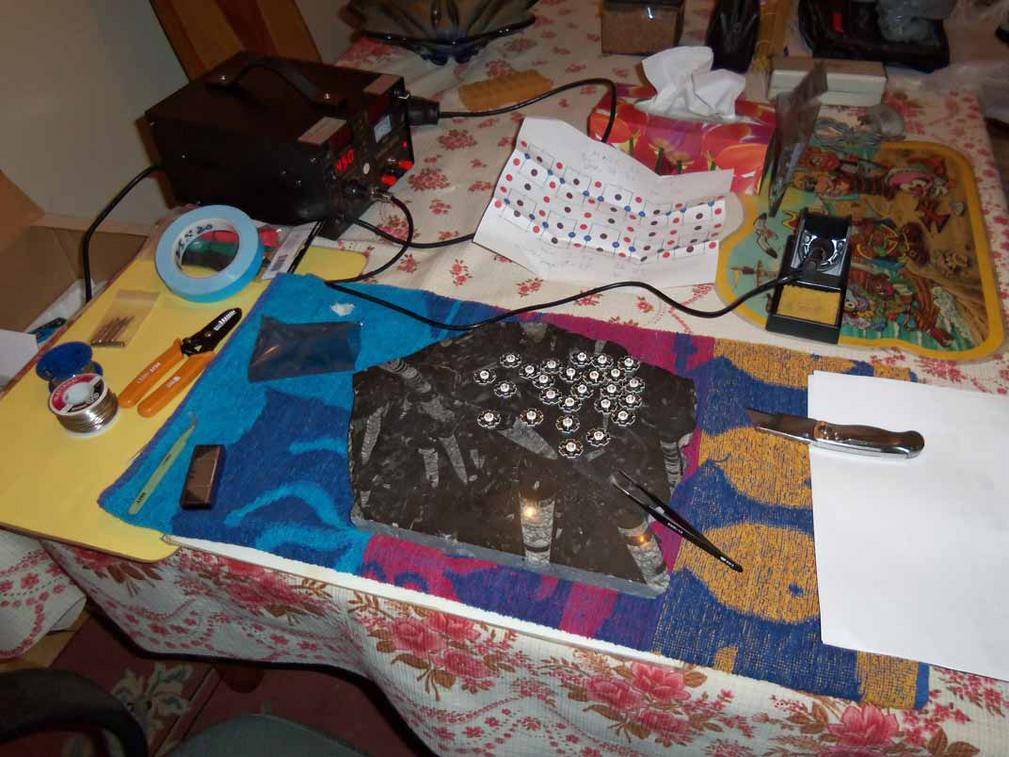
I got the pictures but I need to go buy a continuity tester and see why this shit won't light up.. I got the whites all hooked up together and yes, I know the wires could be shorter and neater looking but again...we come back to the same old thing I've been saying that this is a tester unit to work out bugs and shit like this which happened..
Also, took a picture of the 'work area' where I place a stone which actually has real fossils in it.. I use it for pre-soldering the contacts. The only issue I have with it is that the rosin in the solder splatters a bit and catches the stars ever so slightly enough to be a pain in the ass when I want to turn them or move them to bring the next one close to solder..
Oh well...I guess I needed a continuity tester anyway...right??? LMAO...
Here are the pictures..:
If anyone sees anything that sticks out or has had issues when your solder the chips they wont light, please comment...
Thank you all for your advice. You know I appreciate it...
FUCKIN' MURPHY!!!!!!!!!!!!!!
ARGH!!!!
That fucking Murphy!!!!!! I've managed to keep him at bay this whole time and now he strikes...For those of you who do not know Murphy...he is the guy who said,,,,,,'If it can go wrong, it will go wrong'..LOL
I got the pictures but I need to go buy a continuity tester and see why this shit won't light up.. I got the whites all hooked up together and yes, I know the wires could be shorter and neater looking but again...we come back to the same old thing I've been saying that this is a tester unit to work out bugs and shit like this which happened..
Also, took a picture of the 'work area' where I place a stone which actually has real fossils in it.. I use it for pre-soldering the contacts. The only issue I have with it is that the rosin in the solder splatters a bit and catches the stars ever so slightly enough to be a pain in the ass when I want to turn them or move them to bring the next one close to solder..
Oh well...I guess I needed a continuity tester anyway...right??? LMAO...
Here are the pictures..:
If anyone sees anything that sticks out or has had issues when your solder the chips they wont light, please comment...
Thank you all for your advice. You know I appreciate it...
I would just about bet that one of those little bastards has the polarity reversed. Do you have a volt meter? You should be able to attach one probe to the lead coming from the power supply and, starting at the opposite end, sequentially probe each of the stars in the series - when your voltage drops to zero, that one is either blown or reversed. If you've been handling them without taking precautions to dissipate static, you may have fragged one or more of them if the MCPCBs don't have onboard zeners.
hey hey...lookie what I done..
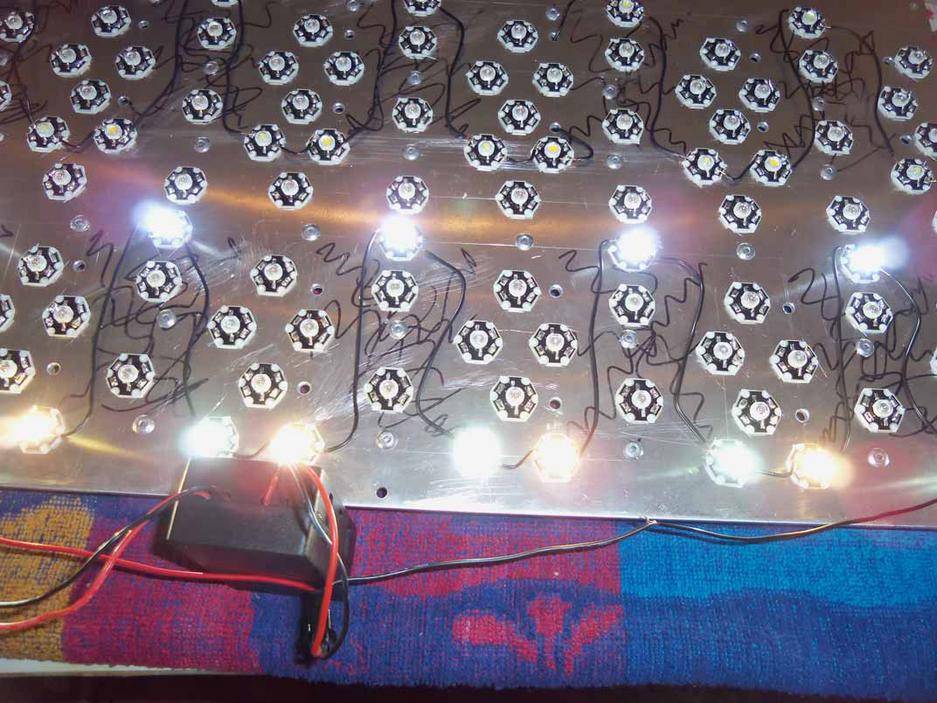
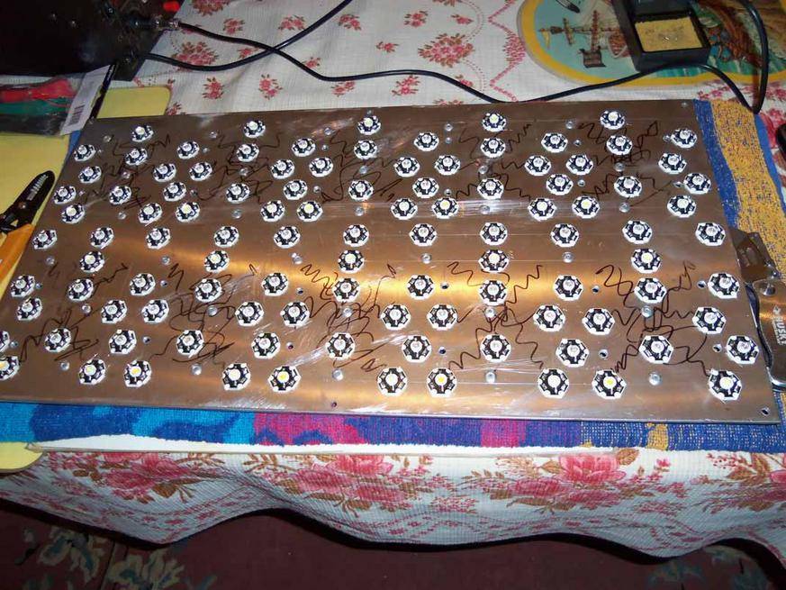
It's not the polarity..What I totally forgot was I have that damn DC voltage tester on my soldering station!!! LOL...I went and tested each one, then I started testing them two at a time...When I got to the end ones...kinda hard to explain..
You see I have the light basically split into five rectangles on either side right....well, connecting the last one in the series on top with the first one on the bottom was the problem...but........here's the catch... it was doing it on both ends so that lead me to think that the wire gauge wasn't heavy enough.
I broke the connections there so I would be running five 'rectangles' or 15 chips on a driver and VOILA!!!!!! worked!! I only snapped the one picture because I was just flashing the lights and kinda hard to snap pictures and hold 4 wires with the other hand trying to hold the one on the contact as well...aahahahh...yeah..sounds fucked up but it worked..
The only problem now is I have to see if upping the wire gauge will fix the issue because if it doesn't, I'll have to buy more drivers and I really don't want to do that...tick toc you know...times 'a wastin'...
The only problem now is I have to see if upping the wire gauge will fix the issue because if it doesn't, I'll have to buy more drivers and I really don't want to do that...tick toc you know...times 'a wastin'...
I think that you have something going on other than wire gauge - that might make it dim, but it wouldn't completely fail to light. If you use your power supply in place of the driver, does it have an ammeter on it to see if you were getting any current flow? It sounds to me like one of the groups was reversed, but perhaps not.
I think that you have something going on other than wire gauge - that might make it dim, but it wouldn't completely fail to light. If you use your power supply in place of the driver, does it have an ammeter on it to see if you were getting any current flow? It sounds to me like one of the groups was reversed, but perhaps not.
Yeah, the more I think about it, the more it sounds and looks like something is off but on both sides in the same location??
No, I don't have an ammeter......yet that is..
.......I'll figure it out. At least now I know it's not my soldering.. I nearly crapped myself when I hooked up the driver and........nothing...almost cried actually LOL....then after the initial let down, I got down to troubleshooting. You're right though, if it was wire gauge related, it would at least be a dim light, not no light at all...there always is that one chance in who knows how much that by some fluke, the polarity is off on both of them and they are located in the same spot on the board...small slim fluky but still it exists.. You know I wont stop until I figure it out and let you all know..
tenthirty
Member
I always go through and test each led with a pair of aa batteries in a little holder using extended connections. (test the wire and the led, from each far side, if you know what I mean)
You can also test the driver with a volt meter and start jumpering out leds from one end. (don't short the whole string, but jumper across one or two leds to see if the rest light up.
You can also test the driver with a volt meter and start jumpering out leds from one end. (don't short the whole string, but jumper across one or two leds to see if the rest light up.
I always go through and test each led with a pair of aa batteries in a little holder using extended connections. (test the wire and the led, from each far side, if you know what I mean)
Exactly this advise I was willing to give you Mr. Vukman ! IT's better to know that all components are ok before putting them all together.
If the driver is dead and you don't want to replace it , you could always use the 'diode' method to assure just the right voltage for your LED chain (I can help you calculate how many diodes are necessary for this - but keep in mind that a cheap rectifier diode have a forward voltage of 0.8-0.9V; but as tenthirty said, you could also use some Zenner diodes for a more accurate circuit).
You can take a look inside the driver just to be sure that the wires are well soldered on the PCB, that there is imperfect soldering, if some components have visible damage or any other clue that can direct you to the cause of problem.
One important thing : some of this drivers do not function at all if you exceed the numbers of the LEDs connected in series as load, and this because they must reach the working current to begin oscillating (and cut the current at high frequency to limit it's value).
Keep up the good work !
Last edited:


Latest posts
-
 Post your Reviews of Romulan Genetics, Romulan BX1
- Latest: EastCoastGambit
-

-
-

Latest posts
-
Post your Reviews of Romulan Genetics, Romulan BX1
- Latest: EastCoastGambit
-
-
-
