What's new
  • Happy Birthday ICMag! Been 20 years since Gypsy Nirvana created the forum! We are celebrating with a 4/20 Giveaway and by launching a new Patreon tier called "420club". You can read more here.
  • Important notice: ICMag's T.O.U. has been updated. Please review it here. For your convenience, it is also available in the main forum menu, under 'Quick Links"!

Krypto's Ultimate Controler

Budweiser13

Active member
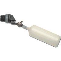
Blinddate are you blind j/k. Any way i ve seen these systems and I cant totally explain why but it needs to be built the way krypto explains. Dude you should really build it your way, show everyone nice pictures of your system built your way with big buds in your system with your float switch...................gooduck to you....... :joint:
 
G

Guest

BlindDate said:
Somebody, please, please explain why you would want to use Electronic float switches, relays, wiring, black boxes, etc, when a simple mechanical Float Valve like this in your controller bucket will do the same thing? I am listening with an open mind.

The float that you posted is used for topping off. The reason for the float swithced is to pump out of the Rez tank and fill the controller unit. Then once the controller is filled. The float switch turns off the fill pump and gravity flows the nutz to all the grow buckets. Once the time has passed the time that is set. The drain pump turns on and start to pump out the nutz out of the controller bucket back into the rez tank. This draws out the nutz out of all the grow buckets. Once the level in the controller bucket gets to the float switch level. The drain pump is then turned off. I hope i got this right. If i explain sometime in the wrong order or totally wrong. Could someone correct me please. Thanks and take care

PS, I got my relay's in today. All i'm waiting on now, is my timer. That should be in no later then friday.
Take care
 
G

Guest

BlindDate said:
Somebody, please, please explain why you would want to use Electronic float switches, relays, wiring, black boxes, etc, when a simple mechanical Float Valve like this in your controller bucket will do the same thing? I am listening with an open mind.

That will do the same things as the switches, timers et all???

I'd have to kindly ask you to leave this thread to those who want to learn how to build this type of controler.
If the way you build it is so much easier and works just as well then why don't you post a thread detailing the build?

All the time you are spending posting your doubts here could be better put to use by writing your own tutorial.


I just thwacked these last week.

I got a little freaked when OG went down so I cleaned house. For about two days. LOL Once my head cleared I decided to fire the lights back up.
I had some Jack's Surprise, Cali-O and BlueBerry going. When OG went down I threw it all in a bunch, couldn't get a good fire going so I stuck it in my Propane grill outdoors with temps in the mid 20's.
To my surprise, two days later many of them still looked viable. :woohoo:
I know which one is the BlueBerry bye the looks of her stature and growth characteristics but the JS and Cali-O look a lot alike so I just call it all Surprise - Surprise.

Anywho, this system is so reliable I now have four of them, two I've purchased and two I've made.

The two I've made, the last one is the one shown here, were made to accomodate 3.5 gallon buckets, rather then the two gallon buckets the purchased version comes with. After running a couple of gardens through using the 3.5 gallon containers, I see no advantage to using the larger containers over the 2 gallon ones. Using the larger containers I see not much difference in plant size and yield, the larger containers have a much greater water requirement, therefore your system requires more maintainence.
I would only use the larger size containers if I were to want to grow less but larger plants which would need to be vegged longer than what I normally do.
My normal routine is once 4 to 6 inch cuttings have established roots and have been transplanted they are set into flowering approximately ten days after being transplanted, at which time they are approximately 12 inches tall. At finish the mostly indica varieties are on average approximately 3 feet tall depending on strain used.

One things that does help is that once your plants have rooted into the pots the pots should be raised higher than the controler by placing a 1 inch spacer under the buckets which your plants are growing in. I use a piece of 1 X 8 cut to length. This is not necessary but does aide in allowing as much water to leave the vessel as possible.


:woohoo: :woohoo: :woohoo: :woohoo:
 
G

Guest

As an experiment I filled 5 of the same 2 gallon containers with and organic soil mix and tossed them in the room with the multi flow.
Same veg time, same flowering time.
 
G

Guest

Afternoon Kryptonite, love the thread and glad to see it still around. Really looking forward to building my system soon. Just waiting on the timer and should be here any day. Going to make alittle different changes to my system, but i'm going to do my own thread with changes. I'll link it here for anyone wanting to check it out. I was really happy when i first came across this thread. Nice to still see it around. Your gard looks nice and happy. Can't wait to see what i can do with this system. I love the 3x3 Ebb & Flo systems and i can't wait to see what i can do with this system. Thanks again for your info and help.
Take care,
BG
 

bartender187

Bakin in da Sun
Veteran
BG- be sure to post that thread, ide love to see your modifications, as im sure others would too. cant wait to see them in action
 

Budweiser13

Active member
Damn Kryptonite, you are the master of the multi flow nice looking grow thanks for your contributions with this tutorial it kicks ass........ :woohoo:
 

Nugs-N-Jugs

Member
Kryptonite, first off very cool of you to share your time and knowledge, thanks. Now a couple of questions. I want to run a modified DWC witha chiller. My system requires that my main rez sit below my controller and buckets.
1. Would your controller allow me to fill my system from my rez below it?
2. How can I safely incorporate the chiller into the system?

I can almost see the "pump off" or "pump out" relay running a valve to gravity drain the system back to the rez instead of pumping it. The chiller thing is another story. How do I incorporate the chiller? I need a "base" amount of water to run through the chiller so it doesn't run dry. Your thoughts!!!
 

BlindDate

Active member
Veteran
KISS

KISS

The float that you posted is used for topping off. The reason for the float swithced is to pump out of the Rez tank and fill the controller unit. Then once the controller is filled. The float switch turns off the fill pump and gravity flows the nutz to all the grow buckets. Once the time has passed the time that is set. The drain pump turns on and start to pump out the nutz out of the controller bucket back into the rez tank. This draws out the nutz out of all the grow buckets. Once the level in the controller bucket gets to the float switch level. The drain pump is then turned off. I hope i got this right. If i explain sometime in the wrong order or totally wrong. Could someone correct me please. Thanks and take care

OK, Krypto, I'm gone. I do not intend to be disruptive, but when I see something really dumb, I just have to say it.

Look guys.....There is nothing special about what you are doing. Think about it. You are simply shifting water back and forth between the Res and the controler bucket. One pump moves it one way, and the other pump moves it the other way. All that is needed is to put the pumps on timers that will alternate the nutrients. Also, a float valve so that the smaller container (the controler bucket) does not overflow. "MY" system does not need to be built anymore than you need to build a wheel to prove that it will roll. It is so unbelievably simple.

But if you guys are dead set on making something that is so absolutely simple into something complex and unnessessary, then I would suggest using infared sensors. Plug them into a data aquisition and control system powered by you PC. Write a basic program to control the watering cycles and have fun!

Go back and read my original posts, and then for those of you that just can't "get it" I suggest that you might like this board game.


Last edited:

packn2puff

IC Official Assistant to the Insistent
Veteran
In a Nutshell

In a Nutshell

Maybe some just don't understand how this controller works and why two sensors instead of just one per circuit..
Gonna borrow some pics from this thread..

Step by Step this is what is happening..

1st the timer


Pins 1 & 2 power for the timer motor
pin 5 the switch common contact (wiper), (hot) Line connected here
pin 4 has contact with pin 5 when timer off (or power out when off)
pin 3 has contact with pin 5 when timer on (power out when on)

Relay DPDT (can use a DPST NO (normally open) as well):
Pin 7 Relay Coil (power across 7 & 8) turns on relay and makes contacts
3 & 5 make and 4 & 6 make when relay is on..no contact (open) when relay is off
Relay A controls Drain pump...Relay B controls Fill pump
Note: If switches tried to control the pump directly..you would probably burn up the contacts..relay handles that load

Float switches:
If float is away from C clip, nearer to base...contact is made.. if near clip, open connection..(makes when magnet is in the middle)
Two top switches belong to the fill circuit..two bottom belong to the drain circuit..
High Level Switches(at height of system fill)..control fill circuit...slightly staggered so HLH sensor trip point is slightly higher than HLL
No water in bucket both switches made by gravity
Low Level Switches(bottom of bucket)..installed upside down..LLL slightly lower than LLH
Why two switches? we'll get to that..


So here we go
Timer turns on..power is now on pin 3 of timer..which is connected to pin 6 of Relay B
When the relay is on..6 & 4 make and the pump is powered..
Relay comes on because the High Low Level (HLL) switch also powered by the timer is made..(bucket is empty)..and powers pin 7(coil)
At the same time a holding circuit is created by timer power on pin 5 making with pin 3 through the (HLH) switch to the relay coil pin 7..
This means now you can open the HLL now because the HLH now has control of the relay..and now powers pin 7
Water fills till it trips the HLH..contacts open..pin 7 loses power..the relay shuts off..pump stops filling
(Here is why two switches) now say the water level drops a bit and timer is still on..
the pump would surge on and off each time the HLH bobbed just a little..
With this circuit, for the pump to come back on, the water has to drop below the HLL before the pump will come back on..
This spacing between the two switches creates a hysteresis
The HLH can bob all it wants, it has no power once the relay went off because 3 & 5 opened..the HLL has to start the holding circuit again to get HLH power..
If you have ever used a large power tool or machinery that has a separate "Start" & "Stop" buttons..it's the same thing..
Once you hit "stop" it won't start again no matter how many times you push "stop" and vice-verse..Start starts..Stop stops
Basically the HLL is the Start Button .. HLH is the stop..
Timer turns off
Power now on pin 4 of timer..Switches LLH & LLL are made because they are upside down and floating (away from the C clip)Bucket is full
Relay A turns on..6 & 4 make..Drain pump power and 3 & 5 make..
and same holding circuit created on Relay A as on B..LLH is the start...LLL is the Stop..
Bucket is empty..now power will remain on the Drain circuit as long as the timer is off..
So if the buckets are slow to drain and fills the control bucket till it reaches the LLH trip point again..the drain pump will cycle back on
and run till the LLL shuts it off again..Automatically keeping the system drained..

Hope this helps some understand some of the monkey motion.. :monkeyeat

A single switch controlling the relay..would cause the system to hammer the pump on and off at the trip point..

Got to go play a game of Mouse Trap.. :wave:

Does this sound right Krypt.. :chin:
 
Last edited:
G

Guest

Nugs-N-Jugs said:
Kryptonite, first off very cool of you to share your time and knowledge, thanks. Now a couple of questions. I want to run a modified DWC witha chiller. My system requires that my main rez sit below my controller and buckets.
1. Would your controller allow me to fill my system from my rez below it?
2. How can I safely incorporate the chiller into the system?

I can almost see the "pump off" or "pump out" relay running a valve to gravity drain the system back to the rez instead of pumping it. The chiller thing is another story. How do I incorporate the chiller? I need a "base" amount of water to run through the chiller so it doesn't run dry. Your thoughts!!!

Your reserviour can be anywhere you want as long as the pumps you are using are powerful enough to push the water that far. What matters is that he controler and buckets are near level with each other.

Never used a chiller .
 
G

Guest

packn2puff said:
Maybe some just don't understand how this controller works and why two sensors instead of just one per circuit..
Gonna borrow some pics from this thread..

Step by Step this is what is happening..

1st the timer


Pins 1 & 2 power for the timer motor
pin 5 the switch common contact (wiper), (hot) Line connected here
pin 4 has contact with pin 5 when timer off (or power out when off)
pin 3 has contact with pin 5 when timer on (power out when on)

Relay DPDT (can use a DPST NO (normally open) as well):
Pin 7 Relay Coil (power across 7 & 8) turns on relay and makes contacts
3 & 5 make and 4 & 6 make when relay is on..no contact (open) when relay is off
Relay A controls Drain pump...Relay B controls Fill pump
Note: If switches tried to control the pump directly..you would probably burn up the contacts..relay handles that load

Float switches:
If float is away from C clip, nearer to base...contact is made.. if near clip, open connection..(makes when magnet is in the middle)
Two top switches belong to the fill circuit..two bottom belong to the drain circuit..
High Level Switches(at height of system fill)..control fill circuit...slightly staggered so HLH sensor trip point is slightly higher than HLL
No water in bucket both switches made by gravity
Low Level Switches(bottom of bucket)..installed upside down..LLL slightly lower than LLH
Why two switches? we'll get to that..


So here we go
Timer turns on..power is now on pin 3 of timer..which is connected to pin 6 of Relay B
When the relay is on..6 & 4 make and the pump is powered..
Relay comes on because the High Low Level (HLL) switch also powered by the timer is made..(bucket is empty)..and powers pin 7(coil)
At the same time a holding circuit is created by timer power on pin 5 making with pin 3 through the (HLH) switch to the relay coil pin 7..
This means now you can open the HLL now because the HLH now has control of the relay..and now powers pin 7
Water fills till it trips the HLH..contacts open..pin 7 loses power..the relay shuts off..pump stops filling
(Here is why two switches) now say the water level drops a bit and timer is still on..
the pump would surge on and off each time the HLH bobbed just a little..
With this circuit, for the pump to come back on, the water has to drop below the HLL before the pump will come back on..
This spacing between the two switches creates a hysteresis
The HLH can bob all it wants, it has no power once the relay went off because 3 & 5 opened..the HLL has to start the holding circuit again to get HLH power..
If you have ever used a large power tool or machinery that has a separate "Start" & "Stop" buttons..it's the same thing..
Once you hit "stop" it won't start again no matter how many times you push "stop" and vice-verse..Start starts..Stop stops
Basically the HLL is the Start Button .. HLH is the stop..
Timer turns off
Power now on pin 4 of timer..Switches LLH & LLL are made because they are upside down and floating (away from the C clip)Bucket is full
Relay A turns on..6 & 4 make..Drain pump power and 3 & 5 make..
and same holding circuit created on Relay A as on B..LLH is the start...LLL is the Stop..
Bucket is empty..now power will remain on the Drain circuit as long as the timer is off..
So if the buckets are slow to drain and fills the control bucket till it reaches the LLH trip point again..the drain pump will cycle back on
and run till the LLL shuts it off again..Automatically keeping the system drained..

Hope this helps some understand some of the monkey motion.. :monkeyeat

A single switch controlling the relay..would cause the system to hammer the pump on and off at the trip point..

Got to go play a game of Mouse Trap.. :wave:

Does this sound right Krypt.. :chin:


Good deal . :tup::tup:
 

packn2puff

IC Official Assistant to the Insistent
Veteran
Kryptonite Is Saving You Money..Why the hatin..

Kryptonite Is Saving You Money..Why the hatin..

I love this multi-flow set-up..when I go that way...I am gonna build this controller..The circuit is a standard "Start" / "Stop" motor control circuit..
I don't understand where dangerous comes from..More like cost effective and simple smooth operation..
This circuit will easily allow a sensor retrofit..if solid state sensors wanted to be used instead..
or modified to use lower voltage to switches and relay coil..
As an electronic tech I see this controller to be sound in design...and easy to adjust..
Seems if for some reason the grow buckets didn't fill as quick as they should..
You could just allow two consecutive timer "On" cycles and the Level Switches would take care of the slow fill problem..
by topping up..and allowing time for gravity to fill the grow buckets..
Drain already will do this because the timer is usually off..powering the Drain circuit..

Ghetto..maybe cause it's DIY..But by design..far from ghetto..simple, effective and solid..
Plug it into a GFIC and she should be safe...
Price a multi-flow system..$$$..building this would be only a small fraction of the cost..

Sgt.Stedenko..Schematic is true..Good job man...made understanding the operation so much easier..at least for me.. :wave:
 

.:Nerve:.

Member
Hey Krypto!
Damn it's GOOD to see you again mate! How have you been?
Very interesting thread this one, havent read it all yet, but im working on it.
It's a looong thread, hehe.

Love - [Myskonoid] (Please say you remember me from OG a couple of years back!)
 

Kryptonite

Active member
.:Nerve:. said:
Hey Krypto!
Damn it's GOOD to see you again mate! How have you been?
Very interesting thread this one, havent read it all yet, but im working on it.
It's a looong thread, hehe.

Love - [Myskonoid] (Please say you remember me from OG a couple of years back!)

How could I forget that thread we had going. LOL .
 

Tomatoesonly

Active member
You guys, Esp. Kryptonite, are just F'n awesome. I stumbled on this thread after many nights thinking just how in the heck a person could copy one of those Multi-flow controller setups. I'm just in awe.
Very interesting on the 2 gal vs. 3.5gal observations, Krypto. I will take your first hand account and build a 2 gal bucket based setup. I assume if this is the case, you would use a 3.5 gal controller bucket similar to the Multi-Flow setup.
 

Kryptonite

Active member
Yes, you would want to use the 3.5 gallon controler for the 2 gallon buckets. You could use a 5 gallon but the floats would still have to be located in the same position as they would be if you were using the smaller 3.5 gallon. You would just have extra space in the top of the controler.
You could even use this controler to flood a large container which would allow you to place the container lower to the floor. This would be an advantage over the traditional ebb and flow which requires the container to be placed on a table reducing your verticle space.

Thanks for the props.
Appreciated. :tup:
 

ButterNBacoN

New member
Your controller is great,works perfect,thought i would give you a heads up on one ov the vendors you recomended, Pool and spa.com, I ordered the timer july 7th, my acount was charged on the 10th, I called to get a tracking # on the 18th,they told me the manufactuer was back ordered then and only then did they send me an email stating such. I called and canceled the order at wich time i asked how long before i recieve my money back and was told that it would be about a week. I have called every week since only to be given the run around, I may never see this money back, so i decided to post my transaction here. I found the same timer at another sight on line thay said they had 100+ in stock cant recall exact number and i was installing it 4 days later,i really wish i had paper work around to give these guyes coodo's but alas, its compost. Just giving my experiances,controller is great and my system is working great, using black lava rock and will be planting in it soon,peace
 
G

Guest

ButterNBacoN said:
Your controller is great,works perfect,thought i would give you a heads up on one ov the vendors you recomended, Pool and spa.com, I ordered the timer july 7th, my acount was charged on the 10th, I called to get a tracking # on the 18th,they told me the manufactuer was back ordered then and only then did they send me an email stating such. I called and canceled the order at wich time i asked how long before i recieve my money back and was told that it would be about a week. I have called every week since only to be given the run around, I may never see this money back, so i decided to post my transaction here. I found the same timer at another sight on line thay said they had 100+ in stock cant recall exact number and i was installing it 4 days later,i really wish i had paper work around to give these guyes coodo's but alas, its compost. Just giving my experiances,controller is great and my system is working great, using black lava rock and will be planting in it soon,peace


I had the same problem with them also. It took like a whole month to get my timer from those A-holes. I'll never order from them again. I did get my timer, but took way to long and i was charged right away and was told they were on back order also. They did e-mail me twice and ask if i wanted my money back, but i told them i was in no rush. I wasn't at the time, so no big deal. There is a problem there and i was say buy some where's else. I'll back up the same problem. Nothing but some bull
Later
 
Top