
malendro
Member
Heatsink: MakersLED 24"
Controller: MakersController
Driver boards: Makers 5Up
Drivers: LDD-1000H
Chips: Cree CXA-2530. 2700k 85CRI
Chip Holders: 180720-0002 By Molex
Thermal paste: ArticSilver5
Additional Cooling: 92m Delta ASB0912H 52CFM
Goals:
370W maximum output
Professional Clean install
No drilling on the shiny metal
Lets get things started with the LEDPorn")
Space LED holders evenly.
Route all internal wires.

Below is the input/output side:
PC fan Molex style connector and pins were to route power.
Controller Signal was routed using something like the 3.5mm adapter shown.
The circular hole was drilled with lots of care and precision for proper alignment so as to limit stresses on the board's components, and the square hole was carved with an Xacto knife for a tight pressure fit. The power input for all the fans is also visible in this picture, it's the white connector on the lower left corner.


Here is the complete mockup.

Controller: MakersController
Driver boards: Makers 5Up
Drivers: LDD-1000H
Chips: Cree CXA-2530. 2700k 85CRI
Chip Holders: 180720-0002 By Molex
Thermal paste: ArticSilver5
Additional Cooling: 92m Delta ASB0912H 52CFM
Goals:
370W maximum output
Professional Clean install
No drilling on the shiny metal
Lets get things started with the LEDPorn
Space LED holders evenly.
Route all internal wires.
Below is the input/output side:
PC fan Molex style connector and pins were to route power.
Controller Signal was routed using something like the 3.5mm adapter shown.
The circular hole was drilled with lots of care and precision for proper alignment so as to limit stresses on the board's components, and the square hole was carved with an Xacto knife for a tight pressure fit. The power input for all the fans is also visible in this picture, it's the white connector on the lower left corner.
Here is the complete mockup.
Attachments
-
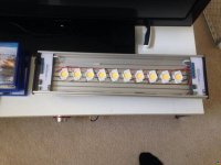 image-1.jpg48.4 KB · Views: 21
 -
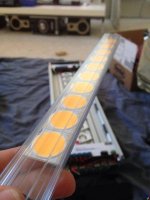 image-3.jpg46.6 KB · Views: 22
 -
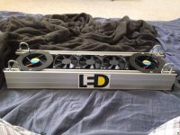 image-4.jpg68.7 KB · Views: 11
 -
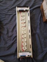 image-5.jpg59.8 KB · Views: 26
 -
 image-7.jpg104.8 KB · Views: 22
 -
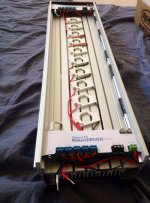 image.jpg68.5 KB · Views: 16
 -
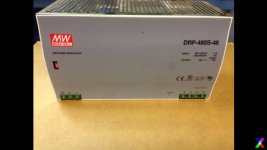 good PSU.jpg26.7 KB · Views: 23
 -
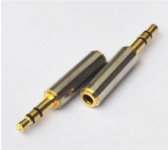 Connector.jpg12.6 KB · Views: 23
 -
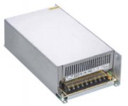 bad PSU.jpg16.7 KB · Views: 18
 -
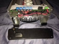 image-2.jpg71 KB · Views: 13

