What's new

Help with timer board issue...

Bodah

Member
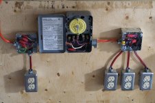
I recently built this 30 amp board... As you can see from the picture it has 1- 120v un-timed receptacle, 1- 120v timed receptacle and 2- 240v timed receptacles... I attempted to plug in my new nanolux ballasts and a warning error flashed saying "open or short circuit"... I havent tested the receptacles with a multi meter but i circuit tested the receptacles and they are all receiving current...

Any help would be GREATLY appreciated...

B~
 

Attachments

  • _DSC0683.jpg
    _DSC0683.jpg
    59.5 KB · Views: 6

imnotcrazy

There is ALWAYS meaning to my madness ®
Veteran
You CAN NOT use a T104 timer for switching 240 and 120 volt circuits at the same time...

They are designed for either one 240V circuit OR 2 x 120V circuits

Where are you pulling the neutral from for the 120V circuit? Is that a 4 wire romex feeding the T104?

Seems to me like you are trying to use a single double pole breaker to power both circuits, can you take a closer pic of the wiring in the timer box? If this is what you have done, the 120V circuit may be causing a voltage drop on one leg of the 220V and the ballast may detect a large variance between phases as an open leg
 

Bodah

Member
It is indeed romex 10/3... I can snap another picture tomorrow as the lights are off atm...

So what you are saying is the 120v receptacle after the timer needs to get removed, but if I was to relocate it alongside the other 120v receptacle before the timer on the opposite leg the variance issue should be resolved, no?

The wiring for the t-104 is as per the diagram included with the unit~

I understand that running a separate circuit for the 120 appliances would be more appropriate, unfortunately there weren't any more slots left on the sub panel. And personally, I thought that running a sub panel off a sub panel seemed a bit redundant. Keeping in mind I calculated the amperage draw of the appliances and it was less than 70% of the maximum for safe constant draw.
 

imnotcrazy

There is ALWAYS meaning to my madness ®
Veteran
You can always get a few "piggy-back" type breakers to free up some space in your panel

Basically it is 2 single pole breakers on a single chassis, this will allow you to open up a space in the panel and then you can wire your necessary 120V circuit either off the open slot you created OR off the open slot on the "Piggy-back" circuit breaker
 

Bodah

Member
I disconnected everything except for the main two 240V receptacles fed via the t-104, via the 10/3 romex and my ballasts are still not even registering current/attempting to fire...

I should also add that everything is fed via 1- 30A stablock breaker, via a 40A sub panel, and circuit tested, all of the recptacles are receiving current.


Danks for any input...


B~
 

Attachments

  • _DSC0684.jpg
    _DSC0684.jpg
    74.9 KB · Views: 7
  • _DSC0686.jpg
    _DSC0686.jpg
    55.2 KB · Views: 6
  • _DSC0687.jpg
    _DSC0687.jpg
    98.4 KB · Views: 7

Bodah

Member
I'm not crazy is CRAZY! 10 seconds with a friend who is an actual electrician spotted the issue~ And you can service both 120 and 240 receptacles through a double phase feed via a t104... Doubt can be a major constrictor of life~ better safe than sorry IMNC~

Cheers,
B~
 

hvac guy

Active member
You can definitely switch both 240V and 120V loads, just don't go over about 30A to 35A total, the t104 is rated for 40A@240V max. Are you using a tandem stablock, might be mounted so it's onlt getting 120V off the bus, move it one space and you'll have both phases from the bus.
 

Latest posts

Latest posts

Top