The gauge isn't an issue - there are basically only two firm color codes in the NEC. White or neutral grey are only to be used for a 120v neutral, and green is for ground. "Phase" tape is available to change the color of an existing wire to indicate that it now has a different purpose. Even black electrical tape wrapped over the exposed white insulation will serve the purpose.

-
Happy Birthday ICMag! Been 20 years since Gypsy Nirvana created the forum! We are celebrating with a 4/20 Giveaway and by launching a new Patreon tier called "420club". You can read more here.
-
Important notice: ICMag's T.O.U. has been updated. Please review it here. For your convenience, it is also available in the main forum menu, under 'Quick Links"!
You are using an out of date browser. It may not display this or other websites correctly.
You should upgrade or use an alternative browser.
You should upgrade or use an alternative browser.
Growroom Electricity and Wiring
- Thread starter Phillthy
- Start date
OK will put a red piece of tape on both ends of the whites to indicate that it hot leg of 240.
Other than that the ground is good?
Yep. Bare copper or green insulation indicate ground.
Green_science
Active member
Electric
Electric
Hey all I am designing a room I have a diagram which i will attach to this post, I know this is messy, and in an ideal world I would run more rings, or even run NO rings, and set up a large board etc, but either way just wondered if some one could confirm that the electric, if perhaps a little naughty, SHOULD work, and maybe add some ideas, the op consist of a veg and bloom room.
PS Do not worry too much about voltage drops the area is not too massive, the longest run will be from Live Feed to veg room cu, perhaps, 50 foot.


Okay so after taking a break and coming back, I am thinking forget the plug sockets and just use terminal blocks for the ring circuits, the reason I was using Heater timers was so I could get to them, but I think scrap the emmersion timers, and just setup DIN mountable contactors and use plugin timers, plugged into the ring I setup for appliances.
Electric
Hey all I am designing a room I have a diagram which i will attach to this post, I know this is messy, and in an ideal world I would run more rings, or even run NO rings, and set up a large board etc, but either way just wondered if some one could confirm that the electric, if perhaps a little naughty, SHOULD work, and maybe add some ideas, the op consist of a veg and bloom room.
PS Do not worry too much about voltage drops the area is not too massive, the longest run will be from Live Feed to veg room cu, perhaps, 50 foot.
Okay so after taking a break and coming back, I am thinking forget the plug sockets and just use terminal blocks for the ring circuits, the reason I was using Heater timers was so I could get to them, but I think scrap the emmersion timers, and just setup DIN mountable contactors and use plugin timers, plugged into the ring I setup for appliances.
HVAC has the right idea here, I think. An installation this large really needs a control system that is going to be very difficult for a non-electrician to put together without a very long learning curve. It really should be integrated with the heating/cooling system and depending on your style of growing, perhaps with the watering system.
Regarding your question, the loads on the phases should be balanced better. Is the 100a service the only power available, or is it just the feed for the lighting? I ask because you have 2 phases pretty much maxed out, and would be concerned about having enough power left for climate control and misc equipment.
Regarding your question, the loads on the phases should be balanced better. Is the 100a service the only power available, or is it just the feed for the lighting? I ask because you have 2 phases pretty much maxed out, and would be concerned about having enough power left for climate control and misc equipment.
Green_science
Active member
Ill keep this short, concerning the flower room, basically with all appliances installed and keeping to 2 CUs, the 2 CUs will be run at a MAX of 80% capacity each, which I know is not regulation, for most equipment, but I will use equipment that can run safely at this capacity, it is not really worth installing a sub CU in the flower room (to help with lights), (from the VEG room CU) as the Veg room CU will be running at around 60% capacity itself, unless you feel it is really worth it to help with load bal, it just means more cables contactors/timers AKA things to go wrong.
I hear ya with climate control, but the rads will be on dedicated rings from the CU's, timed to come on AFTER the lights go out, and go off BEFORE the lights come on.
What I was going to do was bring a ring into the flower room, from the veg room CU, that CU will have about 55A headroom, enough for all appliances and a few 2kw heaters to run with lights on (if needed) if canopy temps are too low during lights on, Ill just smile with joy whilst lowering the lights.
OR do you think I am better off Balancing the light load, VEG and FLOWER room, between 3 CUs EVENLY.
I am not a Pro Sparky, just competent, and heed you're advice I just wanted to give you some more info, to see if you think it's worth it.
Like I said in my first post, I know a install this size should have a control boar, it will just be very long winded, LOTS of cable runs etc etc,
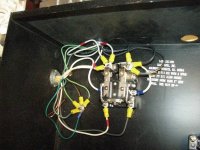
Also I have another question, Diagram attached below,

1. Is it common practice to run ring/looped circuits from the contact, there is no obvious reason, to me, why this is not acceptable.
2. Usually contactors are rated per leg, do you know if this contactor has a MAXIMUM cap of 63a or is it capable of 63a at point 2 and 63a at point 4.
Thanks you for youre time I appreciate it
PS I know there is no reason for the bridge between 1&3, but I was going to draw another ring coming from 4
I hear ya with climate control, but the rads will be on dedicated rings from the CU's, timed to come on AFTER the lights go out, and go off BEFORE the lights come on.
What I was going to do was bring a ring into the flower room, from the veg room CU, that CU will have about 55A headroom, enough for all appliances and a few 2kw heaters to run with lights on (if needed) if canopy temps are too low during lights on, Ill just smile with joy whilst lowering the lights.
OR do you think I am better off Balancing the light load, VEG and FLOWER room, between 3 CUs EVENLY.
I am not a Pro Sparky, just competent, and heed you're advice I just wanted to give you some more info, to see if you think it's worth it.
Like I said in my first post, I know a install this size should have a control boar, it will just be very long winded, LOTS of cable runs etc etc,
Also I have another question, Diagram attached below,
1. Is it common practice to run ring/looped circuits from the contact, there is no obvious reason, to me, why this is not acceptable.
2. Usually contactors are rated per leg, do you know if this contactor has a MAXIMUM cap of 63a or is it capable of 63a at point 2 and 63a at point 4.
Thanks you for youre time I appreciate it
PS I know there is no reason for the bridge between 1&3, but I was going to draw another ring coming from 4
You've lost me with unfamiliar terminology - "rings", "radials", and "CU", which I assume from your drawing is "Consumer Unit" and I still don't know what the hell it is! Are you from Canada by any chance?
It would be one thing to size your fusing down tight to the load from a much larger feeder - it's another matter entirely to design the system right up against the feeder capacity. The NEC stipulates that you do not exceed 80% of the breaker capacity for loads over 3 hours in duration unless you are using a specially listed breaker. If you are in Canada, I don't know what you're ruling authority calls for, but most things seem to be pretty consistent with the US.
Taking a stab at your terms, I would try and keep the loads on all phases balanced as closely as possible all of the time. If you anticipate that no climate control would be needed while the lights are on, then divide the light amongst the phases as evenly as possible. Do the same with heaters and any other appliances that are somewhat predictable. You haven't mentioned air conditioning - that many lights are going to create a hell of a lot of heat.
Looking at the picture of the contactor, I think that "ring" means to feed the circuit from both ends and "radials" are single-ended - correct? This is unnecessary, the only time that I've seen circuits fed from both ends are on tremendously long runs with voltage drop problems (the feeders on a bridge crane that traveled over 1000'). Each set of contacts (1-2 & 3-4) is capable of 63a each. The picture of the breaker wiring is backwards - the top of the breaker (and the contactor) is always the hot side. The control wiring for the contactor is correct.
Green_science
Active member
If I have 3 phase 4 wire supply L1 L2 L3 and N
And the 3 hot phases are 120 degrees offset, this TECHNICALLY means, bar faults and line harmonics, that the heaviest load on a common (shared) N, would be near nothing right.
My scenario is that of above, I am using 100a rated wire for the live phases, I want to use the same 100a cable for the common N, I have heard about overloading N, on lower voltages but for all intents and purposes this is acceptable right. The problem is I understand HID lighting can create harmonics, is it enough of a problem for me to worry about, or is a 100a rated cable for a common N, still quiet safe considering the max load on any live phase will be 72a, Thank you
This one is outside of my direct experience since virtually all of my background is in 3-phase delta systems (no neutral), so if I go astray here hopefully hvac guy can jump in.
My research shows that 480/277 systems are relatively immune from overloading the neutral when powering unbalanced loads or loads that have heavy harmonics. However, 208/120 systems can theoretically see neutral currents up to 130% of the phase loadings under these conditions, but this is apparently exceedingly rare. The critical component in avoiding problems with this is to keep the loads on each phase balanced.
My research shows that 480/277 systems are relatively immune from overloading the neutral when powering unbalanced loads or loads that have heavy harmonics. However, 208/120 systems can theoretically see neutral currents up to 130% of the phase loadings under these conditions, but this is apparently exceedingly rare. The critical component in avoiding problems with this is to keep the loads on each phase balanced.
advanced396
Member
Question for anybody that can help
Looking to connect a high temp shut off to my two DPC 15000 Powerbox lighting controler. Iam running a 14 light flip set up. My question is I have 7 ballast hooked up to one dpc 15000 & the other 7 ballast are hooked up to my second dpc 15000 then going to my two LsM-20 flipboxs
My question is how to connect the high temp shut off to shut down all 14 lights if my ac fails, the problem is that since 7 lights are on one dpc and the other on the second dpc if I connect two high shut off in each room to each dpc for room a, then another two shut offs to room b. Then if one of the rooms trigger the shut off it wont shut down because one of the rooms is always energize the contactor.
Iam using four hot water thermostats with two 50 amp 220V contactors with a 120V coil
Thanks
If you are set up so that you use the normally closed contacts on the thermostats (open on rise), and the DPC15000 is set up so that the input from the thermostats has to be present for the controllers to function, then you would series the wiring from one thermostat to the next. You would come off of your control voltage supply to the first t'stat, then to then next, etc., so that if any one t'stat opens up, the line goes dead.
can anyone please tell me how to properly install a hot/cold digital thermostat for my thermoplus 5 ton a/c
i have 4 wires, 4 colors. green , red, black, white. then the panel has 8 spaces, all with letters on em
thanks
med-man
i have 4 wires, 4 colors. green , red, black, white. then the panel has 8 spaces, all with letters on em
thanks
med-man
nukklehead
Active member
would have thunk a hvac guy would have answered by now med man.. btw I am NOT
but did install my own. the wires usually are for the blower, compressor/condenser, heat coil if you have one, power and ground.. I forget the letter nomenclature but im sure a guy on here can. most thermostats come with instructions and MOST of the time are accurate.
( I had some finagling) if your installation is standard Im sure googling will find it if
a hvac guy doesnt come on here with the right info.. its not that hard and im sure you can
diy... good luck
nukklehead
Active member
Dont know what you mean by water switch.. ( water heater??) I would start by pm Rives and if he doesnt know, he know who will.. good luck bro
can anyone please tell me how to properly install a hot/cold digital thermostat for my thermoplus 5 ton a/c
i have 4 wires, 4 colors. green , red, black, white. then the panel has 8 spaces, all with letters on em
thanks
med-man
send more info plz:
is this new work/retrofit/troubleshoot?
did it work before?
what's the make & model?
which eight letters?
got any pics?
etc.
all this makes it easier to sort out what you've got going on.

Latest posts
-

-

-
Prima esperienza foglie rosse mi devo preoccupare?
- Latest: Dissennatore
-
Latest posts
-
-
-
Prima esperienza foglie rosse mi devo preoccupare?
- Latest: Dissennatore
-
