What's new
  • Happy Birthday ICMag! Been 20 years since Gypsy Nirvana created the forum! We are celebrating with a 4/20 Giveaway and by launching a new Patreon tier called "420club". You can read more here.
  • Important notice: ICMag's T.O.U. has been updated. Please review it here. For your convenience, it is also available in the main forum menu, under 'Quick Links"!

Using a PC power supply as driver?

Slim Picky

New member
Hey hempfield and neekz, thanks for your suggestions. Neekz - I may just use those drivers you mentioned. As you can probably tell electronics is really not my field!

Hempfield - I'm not sure I understand...I can use the 1N4007 for these chips too? But I thought they put out 1A constant current, which is too much for these chips no? I did like you said and bought a bunch of the 1N4007's (250!) so have plenty to mess about with. I just don't follow the part about a self balancing loop. I checked the datasheet and the voltages are as follows; min: 2.7v, typical: 3.2v and max: 3.7v. Though according to the datasheet they can be run up to 1A I think I'd feel far better running them at 0.5A which is what my friend suggested too.

Sorry for such a noob question, I really need an idiots guide here. Maybe I should just go the store bought driver route for these. I'd appreciate if you could enlighten me further.

I will try and put up pictures its just that my shitty phone camera won't cut it and my proper camera is on summer holidays with a friend! Plus I'm a bit paranoid about uploading this kind of stuff.

I wish I was too stoned to continue...lol. I have a rule, I will not buy weed from criminals who spray it with all kinds of crap, the only weed I smoke will be my own grows, and since I don't even have fully functioning lights that is a while away yet! I've decided against the case I first wanted to use, I'm looking for a bigger one for more headroom. They used to be all over the place but when I need one they can't be found anywhere.

Rant over, thanks guys

Slim
 

hempfield

Organic LED Grower
Veteran
The diodes by themselves are not current regulator/limiters, but they can act as ulta fast electronic fuses if the current goes up. Of course, this means that you must find and replace the faulty diode if this occurs.

To answer your question : yes, you can use this cheap diodes connected in series with the leds to power them. To understand how things works, keep in mind that the output voltage of the PC power supply is (or it should be in most cases) constant.
If the power supply output is 5V, then the voltage drop across the entire chain (LED+diodes) will be the same : 5V. If the theoretical sum of the voltage drops of each component ( Vled+n*Vdiode) exceed the power supply voltage, it's impossible for current to rise over a dangerous value and to kill the (expensive) LED. That's why you should experiment and measure the current passing the chain to be sure it does not exceed recommended value (500mA).

If you are sure the typical voltage is 3.2V, you can connect them directly to the 3.3V output, without any concern regarding over current. You still have to measure the current to see if it's close to the typical value.

I'm sorry, but my teaching abilities really sucks ...
 

Slim Picky

New member
Hey hempfield

The more I thought about this the more I figured I needed to know more about what I was attempting since electricity is involved! So after searching I think I have a simple solution.

Please let me know what you think...

I'm going to use an LM317 and resistor to limit the current to each 10w led. The leds claim to be able to handle 900ma but I've decided to limit to 700ma for safety and longevity. However, since the LM317 has a close to 3v voltage drop and the leds use between 9-11v I was thinking to combine the +3.3v and +12v power rails to get +15.3v output and should produce the right voltage for the leds to run. Would this be possible?

I plan on using a 1.8ohm 3watt resistor to limit the current to 700ma.

It's the easiest way I could find with my limited electronics knowledge.

Awaiting your comments/suggestions.

Thanks

Slim
 

hempfield

Organic LED Grower
Veteran
I don't know if it is possible to combine those two outputs (because they have common ground - negative output, so when you will try to connect the positive 3.3V to the negative 12V output , the power supply will enter in short circuit protection ).

Why don't you try to use the other method of current limiting (as in the image below), with a MOSFET transistor (BUZ 11 for example), a simple NPN transistor , a 10k resistor (low power) and a 3W resistor choosen to regulate the current.

picture.php


The value of the current passing the LEDs is given by the formula I=Vbe/R2 , where Vbe is the voltage drop across the base-emiter of the NPN transistor ( which is constant ~0.6V) and the R2 is the load (current sensing) resistor.

If you choose a current of 900mA, the R2 value is 0.6/0.9=0.66 Ohm. This is not an usual value for a resistor, but you can find 0.68Ohm or 0.33Ohm (and use 2 of this type connected in series). I prefer to use two resistors connected in parallel, which split the dissipated power in half.

Don't try to use a variable resistor for R2, cause it will burn for sure.

With this circuit, the only voltage drop will be on R2 (0.6V) and on the MOSFET transistor which will act as a dynamic resistor with a self-controlled loop.

As I already said, I'm not good for teaching, but I will try to explain how this current limiting circuit works :

The MOSFET transistor needs a voltage of at least 4.5V on the gate pin (G) to open. R1 connects the gate to positive +12V (the current passing R1 is extremely low), which cause the MOSFET to open, letting the current flowing through the LED, the MOSFET and the R2 resistor. When the current increase and the voltage drop on the R2 reach ~0.6V , the NPN transistor enter in saturation mod, connecting the gate pin (G) to ground, causing the MOSFET transistor to close and the value of the current to decrease, which also cause a lowering of the voltage drop accros R2, which cause the NPN transistor to close and the loop continues forever.

If you want to play and experiment, you can connect a PWM signal directly to the gate pin (G) to vary the light intensity of the LED (in this case you can eliminate the R1 resistor ) :

picture.php
 

stippy420

New member
Almost got it...

Almost got it...

Wow, just the info I was looking for! You guys rock.

Of course, I have a few questions. (It's been 20+ years since my one electronics class, so please bear with me.) :)

1) The stuff I'm reading, you guys mention one light here, two there, but I can hook up as many LEDs as the power supply can handle, right? Say I use a 1000w power supply (I just happen to have a new one here not being used); can I can pump out up to 1000w at 12v as long as I keep the total amps under the unit's rating? (which is something like 20A per 12v line, 6 12v lines). And no, I'm not going to run anywhere near that many lights!! :D

2) The current limiter for the red LEDs; this is where I lose my ever-so-slight grip on the topic. (The more I read it, the more confused I'm getting.)
Questions on the diagram:
a) R1: 10kOhm resistor... any wattage will do?
b) T2: Any npn transistor? What do I need to look for here, max amp rating? In your math/explanation, you say the voltage drop on the transistor is .6v; I'm assuming that number varies by transistor and I just need to swap that number for the value on whatever transistor I use... or is that somewhat common?
c) T1: Pretend I can't find a BUZ11; I just need something that will handle the total watts and amps, right?
d) R2: 3 Watts is just based on his calculations, right? If I were using leds with 7 volts forward @ 1000mA, I'd need a 5W resistor?

Thanks in advance for your patience and help!! :D
 

hempfield

Organic LED Grower
Veteran
Wow, just the info I was looking for! You guys rock.

Of course, I have a few questions. (It's been 20+ years since my one electronics class, so please bear with me.) :)

1) The stuff I'm reading, you guys mention one light here, two there, but I can hook up as many LEDs as the power supply can handle, right? Say I use a 1000w power supply (I just happen to have a new one here not being used); can I can pump out up to 1000w at 12v as long as I keep the total amps under the unit's rating? (which is something like 20A per 12v line, 6 12v lines). And no, I'm not going to run anywhere near that many lights!! :D
A switching power supply works with maximum efficiency on full power (not peaks), so as long you use proper conductors to transport 20A, it's OK.

2) The current limiter for the red LEDs; this is where I lose my ever-so-slight grip on the topic. (The more I read it, the more confused I'm getting.)
Questions on the diagram:
a) R1: 10kOhm resistor... any wattage will do?
Yes, any wattage. The current passing R1 is almost zero, because the internal resistance of the gate pin is of tens of giga ohms.

b) T2: Any npn transistor? What do I need to look for here, max amp rating? In your math/explanation, you say the voltage drop on the transistor is .6v; I'm assuming that number varies by transistor and I just need to swap that number for the value on whatever transistor I use... or is that somewhat common?
For example you can use BC 546 or equivalent. The 0.6V voltage drop is typical for almost every Silicon transistor and it varies with some mV from model to model.

c) T1: Pretend I can't find a BUZ11; I just need something that will handle the total watts and amps, right?
You will find it for sure, it's a very common and cheap MOSFET transistor. IF not, any N-chanel MOSFET with low RDS ~0.04Ohm (drain to source resistance ) will fit (IRF 510, IRF 520, etc)

d) R2: 3 Watts is just based on his calculations, right? If I were using leds with 7 volts forward @ 1000mA, I'd need a 5W resistor?

Thanks in advance for your patience and help!! :D

The power dissipated on R2 can be calculated with formula : P=I*Vbe , which for a 1000mA current equals 1*0.6=0.6W. The R2 will get warm, eventually hot, but not to hot - so if you see smoke it means you under rate it big time. A 3W resistor does the job pretty fine. The rest of the surplus power will be dissipated by the MOSFET transistor, so you will need a small passive heatsink for it. No need to oversize the heatsink, the transistor will work fine even when hot. But try to mount the NPN transistor closest to the MOSFET. The NPN does not have to handle high currents so it will remain cold, but the amplification factor vary (decrease) with the temp; placing them close to the MOSFET acts as a overload protection. If I remember right, BUZ 11 cand handle up to 10Amps at 30V , so 1Amp will be a child play.

P.S. You can mount the MOSFET transistor on the same heatsink the LEDs will be mounted on, but keep in mind that the metal plate on it's back is electrically connected to the Drain pin so you have to use and insulator like the one in the pic below (they are cheap and you can find them on any electronic components store) :

mosfet510.bmp
mP9gK4_pKRIDwaHseLANryQ.jpg
 
Last edited:

stippy420

New member
Awesome reply, thank you!!

I can't wait to get lights built for my plants... and a new set for my fishtank. Time to order some LEDs! :D


:thank you:
 

stippy420

New member
Hey helpfield, any thoughts on heat dissipation?

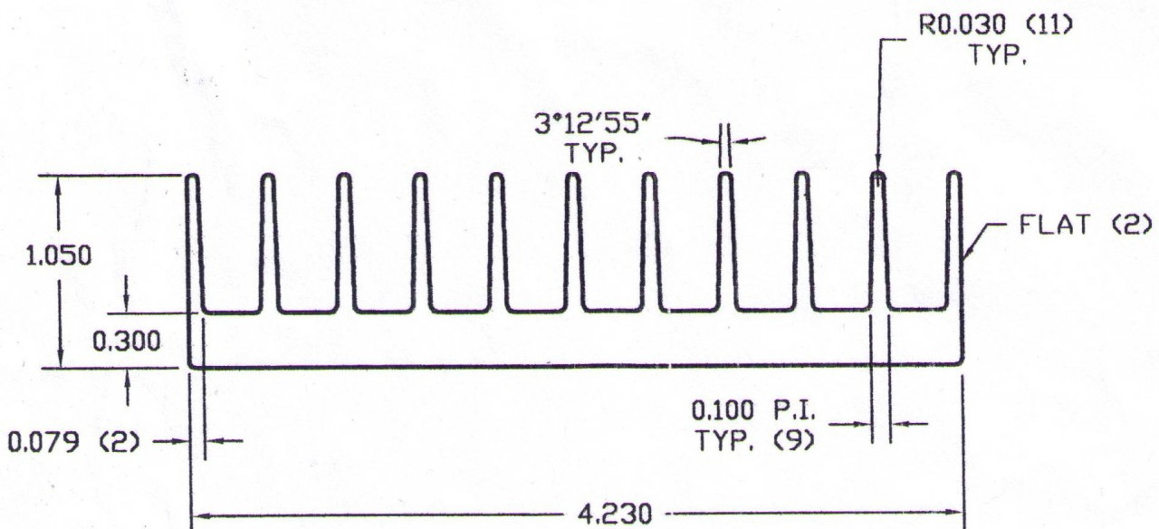
I wanted to use a ~4" x 24" finned aluminum heatsink to hold about 40 10w LEDs. (227w total estimated draw @ 24.5A on a 500w 30A power supply) That would be approx. 2.4" of heatsink per LED. (assuming each LED is 1") I can add 1-2 fans on the heatsink, even thought about adding a cowl to force all the air over the fins. (I only picked this size sink so I could use standard PVC gutters as a cowl.)

Do you think that would be enough cooling or am I insane? Both? :D

This is the heatsink I was thinking of using: C/W/3": approximately 2.15
4.230-cropped__87927__21775__48979.1337878452.1280.1280.jpg
 

stippy420

New member
Pretty sure I was just nuts... or high. lol Going with an 8"x12" aluminum sink, with 1" fins. The heat dissipation is double (1.1 compared to 2.15) as well as doubling the mounting area. Add a few fans and a cowl and I should be good. :)
 

stippy420

New member
Circuit for parallel setup

Circuit for parallel setup

So since I'm using a PC power supply, and therefore running my LEDs in parallel, I can't use that circuit design; it's for LEDs in series. I found this for a parallel circuit setup...
current-limiter-discrete.png


...but I don't know how to find the value for Rs... I'm assuming it's the same as Re (.68 Ohm @ .54w if I did it right, R2 on your diagram) but I'd really like to confirm before I start soldering away. :) (My red LEDs are 6-7v @900Ma)

Using the above as reference;
Source: 12v
Rb: 10k Ohm resistor
Rs and Re: .68 Ohm resistors - ???
Tp: BUZ11 trasistor (50W/30A)
Ts: NPN transistor

Thanks in advance!! (and I apologize if this is an obvious answer and I'm just not getting it!)
 
Top