What's new
  • Happy Birthday ICMag! Been 20 years since Gypsy Nirvana created the forum! We are celebrating with a 4/20 Giveaway and by launching a new Patreon tier called "420club". You can read more here.
  • Important notice: ICMag's T.O.U. has been updated. Please review it here. For your convenience, it is also available in the main forum menu, under 'Quick Links"!

HELP! need some help with a small electrical job

gaiusmarius

me
Veteran
i need to make use of a cable that was installed by an electrician years and years ago. it has 5 wires inside. but i only need to use it to power a normal plug. so my question is how do i go from a 5 polled cable to a three polled cable. have just used the socket in the wall, but if someone forgets not to use certain other sockets for the vacuum it can be too much. so i want to make use of the safer cable that draws power from the fuse board.

so i want to be able to power this controller:
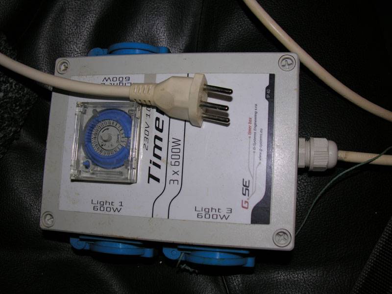
picture.php


from this source.
picture.php

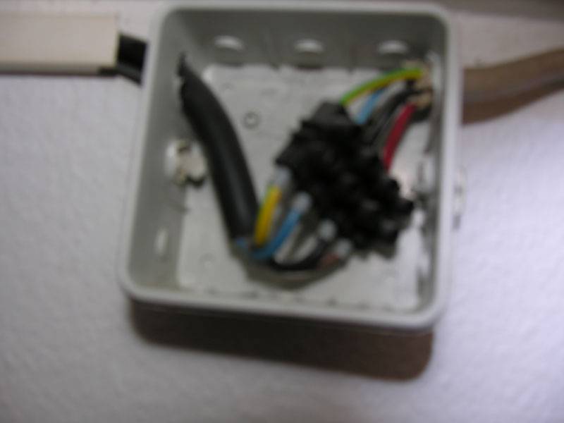
this pic just shows you where it was connected together to make it longer. it ends with one of those black clamp things. so how do i go about this? cut the plug off the controller and then?

any help greatly appreciated, i am sick of changing out the sockets. there will always be someone who uses the wrong plug and over loads the circuit if i power every thing from 1 circuit. that thick 5 polled cable is powered by both circuits.

gaius
 

soursmoker

East Coast, All Day!
Veteran
sorry I can't help but try hitting up rives. He seems to be the go to go around here when it comes to Electricity shit...
 

gaiusmarius

me
Veteran
yeah it is, but we only hooked it up to 2 phases as the electrics are done a bit funny and there are only 2 x 10 amp fuses, if thats what you mean.

sorry for the blurry pic, maybe a better pic will make it more clear. basically that cable is taking power directly from behind my fuse board, it's hooked to the back of two 10 amp fuses. i used to have a bigger controller wired to that cable, but that controller cable also had 5 wires inside the it, so was easy to hook them together. the controller i need to use now is smaller and only has 3 wires inside the cable. before you ask i don't have the old bigger unit anymore.
 

moses wellfleet

Well-known member
Moderator
Veteran
So you are converting 3 phase to single phase. Should be a matter of bridging a couple wires so you are left with one live.
 

gaiusmarius

me
Veteran
so cut the plug off the timer/lamp controller and join 3 wires to the 4 wires? so i have red blue, black and earth, so i suppose i join blue to blue and then the red and black with the red. and earth to earth? so stick the red and black in one end of the joiner and just have the single red in the other other side? seems instinctively dangerous to join 2 wires like that, but maybe thats due to my less then complete understanding of electricity.
 

moses wellfleet

Well-known member
Moderator
Veteran
Ya wait for more input from other members first. I have seen a 3 phase plug connected to a single phase cable before, but I am no expert
 

gaiusmarius

me
Veteran
just to be exact, there are only 4 wires being used inside the thick cable, as can be seen in the blurry pic. i mistakenly wrote 5 in the first post. so it's a matter of connecting 4 wire source cable to a 3 wire fixture/timer/controller what ever it's called.
 

rives

Inveterate Tinkerer
Mentor
ICMag Donor
Veteran
Ok, I'm confused. It looks to me as though the current connection is 4 wires, which here would be 120/240 with a ground. However, it seems to me that you were from across the pond, and I don't think that you guys even use 120v. 3-phase is almost invariably a commercial/industrial power arrangement and is almost unheard of for residential use here. Googling the European wire codes show "old" & "new" versions and unfortunately they have used the same colors but in opposing fashions. The later version uses red, yellow, and blue for hot wires, black for the neutral and yellow/green for the ground. I also see brown, black and gray tossed in as alternate colors for hot wires with blue as the neutral. Do you have a meter and know how to use it? Is there a schematic for the controller that you want to hook up?
 

gaiusmarius

me
Veteran
shit you make it sound complicated.

yes this is Swiss electrics and we have 230V running to every where and 380 is for industrial use.

what i remember from here is that blue is always N. and yellow/green is always earth. i dont know if i still have the papers for the timer controller, all it is is a relay and a good timer powering three plugs.

will look for the schematics.

our normal household currant connection runs with 3 wires. the electrician used 4 wires so he could take power from both fuses instead of just from 1 fuse.

if you need a pic of the cable hooked to the back of the fuse board let me know.
 

rives

Inveterate Tinkerer
Mentor
ICMag Donor
Veteran
shit you make it sound complicated.

yes this is Swiss electrics and we have 230V running to every where and 380 is for industrial use.

what i remember from here is that blue is always N. and yellow/green is always earth. i dont know if i still have the papers for the timer controller, all it is is a relay and a good timer powering three plugs.

will look for the schematics.

our normal household currant connection runs with 3 wires. the electrician used 4 wires so he could take power from both fuses instead of just from 1 fuse.

if you need a pic of the cable hooked to the back of the fuse board let me know.

This sounds similar to our 120/240 - either hot leg to neutral gives you 120v, and from one hot leg to the other gives you 240v. It sounds as though the black and the brown from your large cable should both be hot legs coming from the fuses if the blue is neutral. If this is the case, you should be able to connect your new load by using either the black or the brown for power, the blue for the neutral, and the green/yellow for the ground. Since you don't know how to use your meter, it would be a good idea to verify that the the black and the brown wire connect to the fuses in the distribution panel. A picture of the meter would help if you want to use it to verify what is going on.

If you want to keep the cord to the controller intact, you could take an extension cord and cut it in half, using the female end to connect into the box where the connections are made. This would allow you to just plug your controller in and keep things simple for future changes.
 

gaiusmarius

me
Veteran
but if i use only 1 of the hot wires, i will only be taking power from 1 fuse, i'd like to distribute the load to both fuses so the rest of the house can take power from the sockets without worrying that they will over load the circuit and blow the fuse or melt the wall socket which has happened 3 times in the last few years. is it not possible to combine the 2 hot wires into 1 that hooks up to the controller? or will it already put less strain on the wall sockets if i take the power direct from the fuse board, even if it's just from 1 of the circuits/fuses?
 

rives

Inveterate Tinkerer
Mentor
ICMag Donor
Veteran
but if i use only 1 of the hot wires, i will only be taking power from 1 fuse, i'd like to distribute the load to both fuses so the rest of the house can take power from the sockets without worrying that they will over load the circuit and blow the fuse or melt the wall socket which has happened 3 times in the last few years. is it not possible to combine the 2 hot wires into 1 that hooks up to the controller? or will it already put less strain on the wall sockets if i take the power direct from the fuse board, even if it's just from 1 of the circuits/fuses?

I'm apparently not understanding what you want to do - from what you said up above, I got the impression you wanted to use this cable to power your controller so that it would no longer be plugged into the wall sockets, thus relieving the load on the wall sockets.

You cannot combine two different circuits into a single circuit. You could split the existing circuit feeding your wall sockets into two circuits and power each one from the fuses feeding your cable. Theoretically you could combine the two wires and feed them from a single fuse, and then increase the size of the fuse (parallel the feeders), but you would then exceed the ampacity of the wall sockets. The fuse needs to be sized to be the same rating or less than what the wall socket is capable of handling.

Incidentally, it sounds as though the wall sockets are already inadequately protected - there is no way that you should be melting wall sockets if the fuse is correctly sized other than from loose connections.
 

Ez Rider

Active member
Veteran
I'd look into upgrading the panel if possible. 20A is barely enough to power a bigscreen and a fridge. Like rives says: if your wall sockets are melting, something is obviously wrong, and you are risking the lives and property of everyone in the building, every time you turn the light on. Improperly wired/overcurrent protected growrooms are DANGEROUS. You need to check the size of the main wires entering your panel( a pic of your main panel, and fuses would help), and determine if you have the ability to draw more than the 20A you are fused for now. If so, put in a new panel, and install a new, independent circuit just for your grow. It may cost a few $$(or whatever you use), but you won't be risking life and property every time the light goes on. I had to upgrade my panel, and found it relatively easy. I personally believe that ALL grows should be on an independent sub-panel, with GFIC protection for EVERY circuit.
 

gaiusmarius

me
Veteran
i would normally do just that, ie get it all installed by an electrician, that thick cable was installed by an electrician when i was running more lights in a different room. all the while when i ran it with that cable we never had a problem with the sockets. but since i been running 2 x 600 w as well as a 250w mh plus exhaust and pump over the wall socket it has been happening when someone else uses the sockets powered from the same fuse for something else like the 1800w vacuume cleaner.

before i was running 4 lamps on the fat cable and the sockets never had any problems. so i think it's not the wireing thats the problem it was the overloading the circuit. since i replaced the socket and made sure to divide the power use a bit better all the cables,plugs and sockets are not even getting warm. also these socket melting problems have been years apart. about 3 years ago they even replaced all the wires in the walls with thicker ones. but it does bother me a lot that the socket would melt before the fuse blows, this place still uses the old ceramic fuses that you screw in, will get a pic, i have to unscrew the board it's mounted on else you won't see much, for now i'm checking the wires and socket situation regularly.
 

gaiusmarius

me
Veteran
if that cable is taking power directly from the panel, does it mean it can take up to 10 amps on that cable no mater what else is being drawn over the original electrical system that powers the wall sockets?
 

rives

Inveterate Tinkerer
Mentor
ICMag Donor
Veteran
if that cable is taking power directly from the panel, does it mean it can take up to 10 amps on that cable no mater what else is being drawn over the original electrical system that powers the wall sockets?

Yes. If the cable is independently fused, the rest of the system draw won't have any impact on it.

If you have 1450 watts of lighting hooked up (actually closer to 1600 watts with ballast losses), plus pumps and fans, and then plug in an 1800w vacuum cleaner, the total load is in excess of 15 amps. I don't know what the fuses are for your wall receptacle circuits, but assuming that the receptacles are roughly comparable in capacity to ours, I doubt that the circuit should be over 10 amps. That would give you 2300 watts at 230v. If you are plugging in 150% of that and destroying wall sockets rather than blowing fuses, then something isn't set up properly. You shouldn't have to "be careful" with what you plug in or do regular inspections (although both are good ideas) - the protection should be doing it's job long before you see a component failure.
 

Ez Rider

Active member
Veteran
Yes. If the cable is independently fused, the rest of the system draw won't have any impact on it.

If you have 1450 watts of lighting hooked up (actually closer to 1600 watts with ballast losses), plus pumps and fans, and then plug in an 1800w vacuum cleaner, the total load is in excess of 15 amps. I don't know what the fuses are for your wall receptacle circuits, but assuming that the receptacles are roughly comparable in capacity to ours, I doubt that the circuit should be over 10 amps. That would give you 2300 watts at 230v. If you are plugging in 150% of that and destroying wall sockets rather than blowing fuses, then something isn't set up properly. You shouldn't have to "be careful" with what you plug in or do regular inspections (although both are good ideas) - the protection should be doing it's job long before you see a component failure.

:yeahthats
 

Ez Rider

Active member
Veteran
I think I get it now. You a currently using one "hot leg" from each of your existing 10A/230V circuits to create a "third" circuit for your equipment. You're pulling around 10A just with your grow, so each of your circuits is at 50% capacity just from your grow! You shouldn't EVER take your circuit above 80%. So you've really only got 3A per circuit surpluss when the grow is running. With those OLD style fuses, it's a wonder you haven't had a fire. Assuming the main wires have enough ampacity, tap the main before the existing fuses, and add a small subpanel with a MODERN breaker for your grow. It sounds to me that your electrician must have had something similar set up before. If you provide pics of your existing, I'm sure either Rives or myself can walk you through it. I'm not sure about costs in your country...in the US this would be ~$100 for parts/wire. I also want to be clear that I'm NOT advising you to bypass any metering devices... just the existing(substandard) fuses.
 

Latest posts

Latest posts

Top