
You are using an out of date browser. It may not display this or other websites correctly.
You should upgrade or use an alternative browser.
You should upgrade or use an alternative browser.
Growroom Electricity and Wiring
- Thread starter Phillthy
- Start date
Ok i need some help to check my math .
Room load
1800W HPS (3*600) 8 amp@240V main lighting 1*DP20amp breaker
800W MH (2*400) 3.5 amp@240V sup. lighting
1*DP20amp breaker
525W 4.75amp@110V fans
1*SP15amp breaker
1100W 10 amp@110V A/C
1*SP15amp breaker
1000W 9 amp@110v Dehu
1*SP15amp breaker
200W 2 amp@110v Pump
All component are switch by SSR drived by computer (growtronix)
Main power wire is 8/3(40foots) on 40 amp breaker in main panel pics will be here soon
Place for pics (soon)
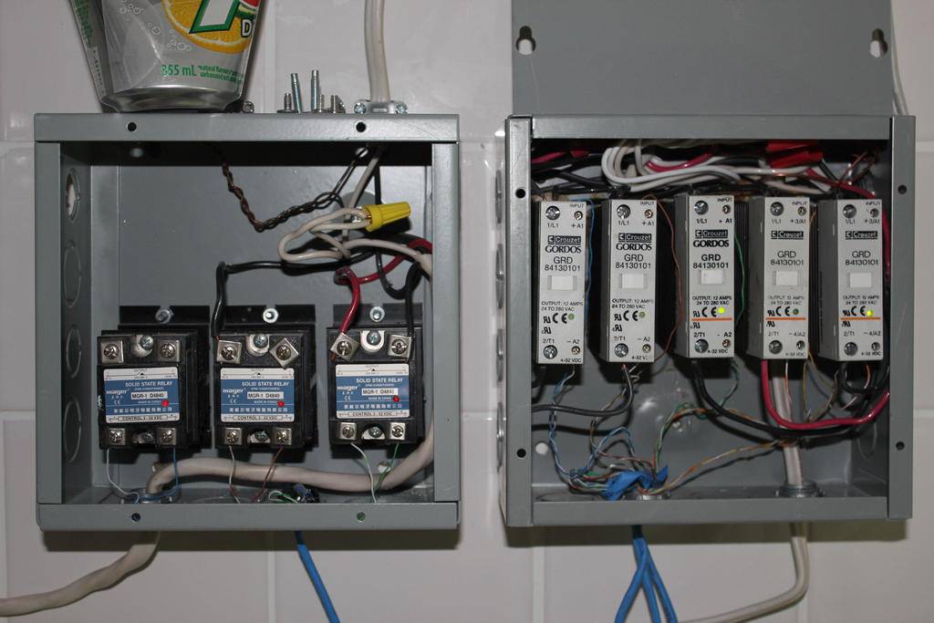
pic #1 SSR first box is feed by 12/3 from 2Sp20 amp.
second box is feed by 14/2 from SP15amp.
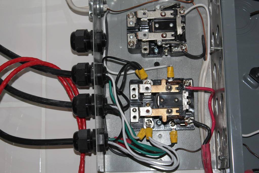
pic #2 Relay for main light feed by 12/2 from DP 20amp.
other relay will be for secondary lighting not wired now
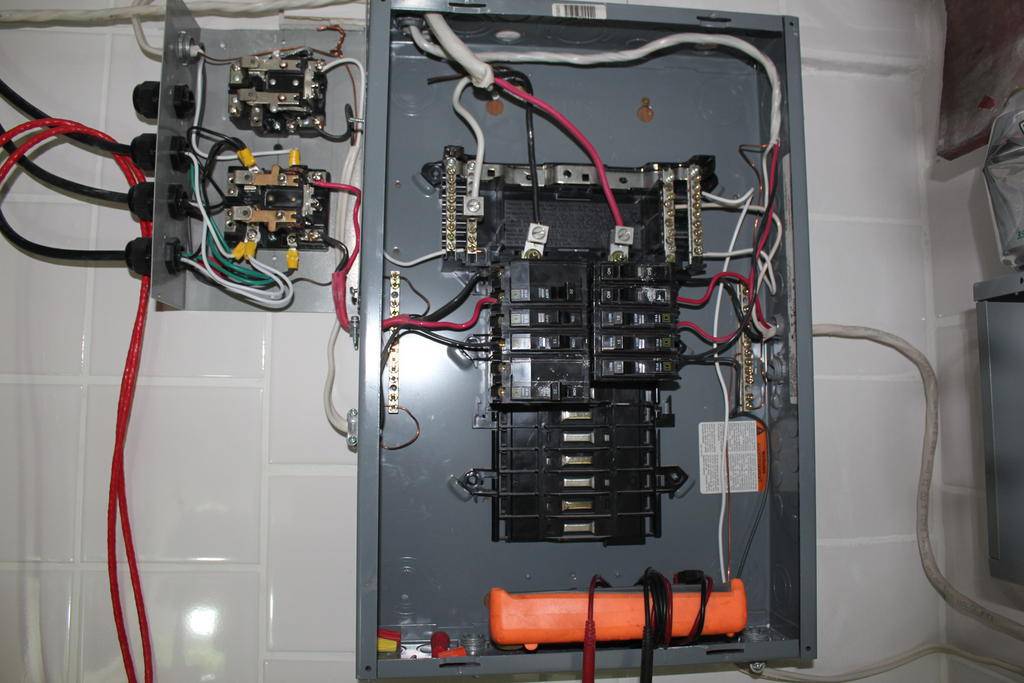
pic #3 main panel
pic #4 switch for ssr

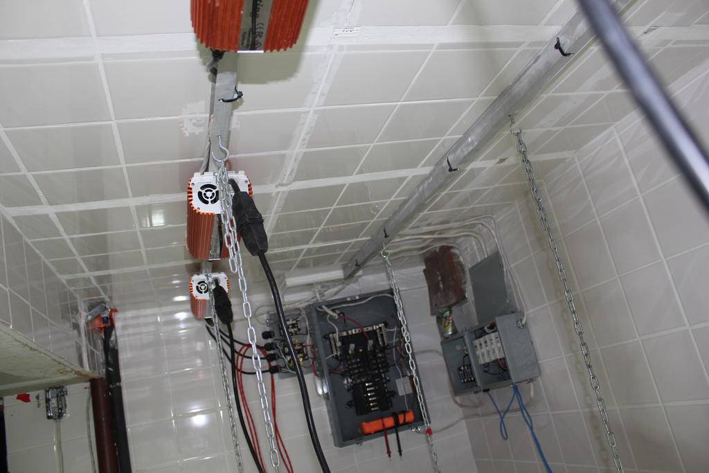
pic #5 main room (still in rebuilt phase almost finish)
pic #1 SSR first box is feed by 12/3 from 2Sp20 amp.
second box is feed by 14/2 from SP15amp.
pic #2 Relay for main light feed by 12/2 from DP 20amp.
other relay will be for secondary lighting not wired now
pic #3 main panel
pic #4 switch for ssr
pic #5 main room (still in rebuilt phase almost finish)
Last edited:
Ok i need some help to check my math
It looks like you've got it. The lighting load is probably going to be a little higher than what you have calculated as a result of ballast losses, but not enough to be a problem, and you will need to balance your 120v loads out on each phase to try and keep the load as even as possible. The load shouldn't be a problem, but do you ever see a need for a heater and have controls in place for it?
Hi RivesIt looks like you've got it. The lighting load is probably going to be a little higher than what you have calculated as a result of ballast losses, but not enough to be a problem, and you will need to balance your 120v loads out on each phase to try and keep the load as even as possible. The load shouldn't be a problem, but do you ever see a need for a heater and have controls in place for it?
yes heater are in project and yes i have control for it S.S.R. check for pics as i have update it just above your post
farmhouse cat
Member
Ive got a question. Excuse my ignorance on the subject.
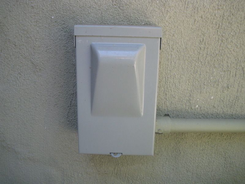
I had my electrician install a 60 amp sub panel in my grow room obviously before start of operation. I instructed him to run 208/230 1 phase 15 amp breaker to a disconnect box outside for my future mini split.
Its 6 months later and im about to purchase a mini split.
This..http://buyriteappliances.com/friedr...h&gdftrk=gdfV23947_a_7c1986_a_7c8120_a_7c7913
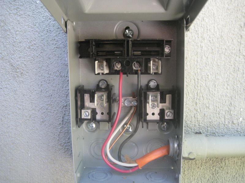
Upon examination of sub panel shown below, the circuit for the disconnect box has a double pole 30 amp breaker??
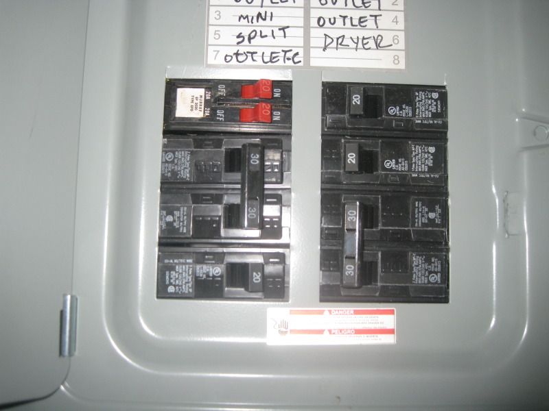
The mini split calls for a 230/208 volt 20 amp circuit breaker. What needs to be done here?
Heres are some pics of the disconnect box.
I had my electrician install a 60 amp sub panel in my grow room obviously before start of operation. I instructed him to run 208/230 1 phase 15 amp breaker to a disconnect box outside for my future mini split.
Its 6 months later and im about to purchase a mini split.
This..http://buyriteappliances.com/friedr...h&gdftrk=gdfV23947_a_7c1986_a_7c8120_a_7c7913
Upon examination of sub panel shown below, the circuit for the disconnect box has a double pole 30 amp breaker??
The mini split calls for a 230/208 volt 20 amp circuit breaker. What needs to be done here?
Heres are some pics of the disconnect box.
The mini split calls for a 230/208 volt 20 amp circuit breaker. What needs to be done here?
FC, check your PM's. The service disconnect in your bottom picture can be fused down to 20a fuses, or the breaker feeding the circuit in the sub-panel could be changed to a 20a breaker. Either one has it's benefits - if you haven't purchased fuses yet, then buying the 20a fuses would be a bit cheaper. If the disconnect came with 30a fuses, then changing out the breaker will give you a protection point that is easily resettable if the circuit trips vs trying to find the appropriate fuses when they blow (or remembering where you put the spares!).
farmhouse cat
Member
Thanks Rives...that cleared things right up! so if i just buy a 20amp fuse, it plugs right into the slot in the disconnect box?
How do i see if what fuses are in the disconnect box? Actuall i think it says 30 amp on the box 2 pics up? So maybe the best thing to do is just swap out the 30amp breaker in the sub panel for a 20? Then its just a matter of hardwiring the mini split in?
How do i see if what fuses are in the disconnect box? Actuall i think it says 30 amp on the box 2 pics up? So maybe the best thing to do is just swap out the 30amp breaker in the sub panel for a 20? Then its just a matter of hardwiring the mini split in?
weeddaddy50
Member
Nice thread
Nice thread
I wish I had this to go by when I built my room.
Nice thread
I wish I had this to go by when I built my room.
Thanks Rives...that cleared things right up! so if i just buy a 20amp fuse, it plugs right into the slot in the disconnect box?
How do i see if what fuses are in the disconnect box? Actuall i think it says 30 amp on the box 2 pics up? So maybe the best thing to do is just swap out the 30amp breaker in the sub panel for a 20? Then its just a matter of hardwiring the mini split in?
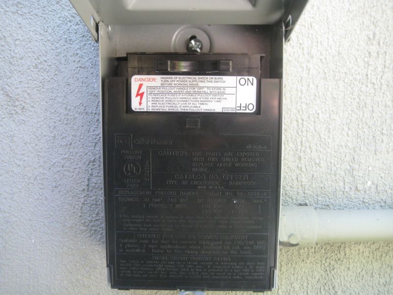
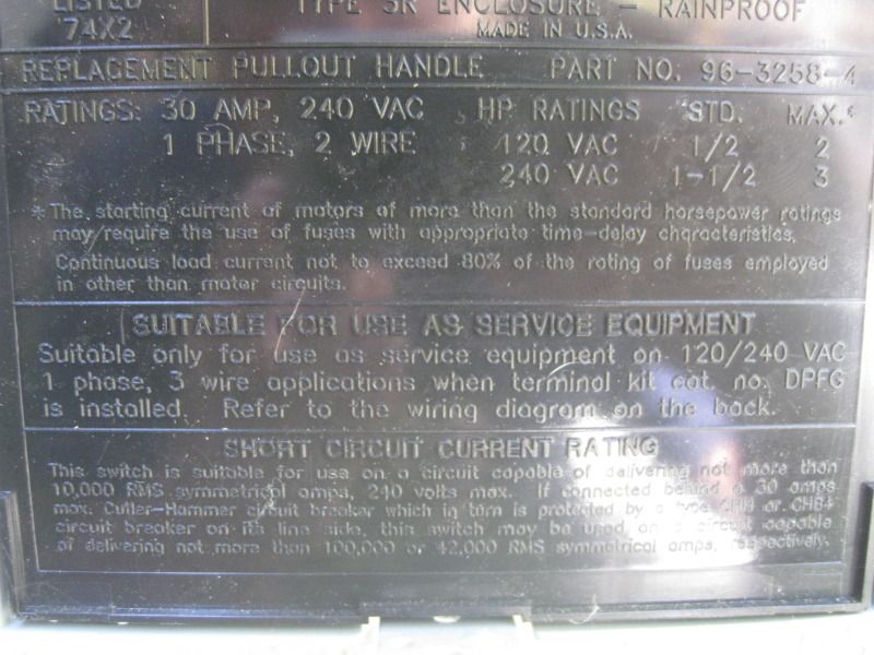
You are going to need some fuses for the disconnect but there may be some there already - they may be in the back side of the black insert that you pulled out to show the connection points. There should be two, one for each hot leg, and they will go into the semi-circular clips on the outboard side of each wire and extend from there down into the lower clips on each side. The 30 amps written on the insert is a maximum, you can use a lighter fuse as long as the dimensions are the same.
Hi Rives
yes heater are in project and yes i have control for it S.S.R. check for pics as i have update it just above your post
OBJ, are those SSR's going to have enough airflow to keep the heat sinks cool once you get the cover on the box? Project looks great!
farmhouse cat
Member
You are going to need some fuses for the disconnect but there may be some there already - they may be in the back side of the black insert that you pulled out to show the connection points. There should be two, one for each hot leg, and they will go into the semi-circular clips on the outboard side of each wire and extend from there down into the lower clips on each side. The 30 amps written on the insert is a maximum, you can use a lighter fuse as long as the dimensions are the same.
I see..it looks like i will need to buy some as there is none in the box.
I take it, i will need two 20amp fuses? , but use just one side?
I see..it looks like i will need to buy some as there is none in the box.
I take it, i will need two 20amp fuses? , but use just one side?
I'm not sure what you mean by use just one side. You will need both the red and the black wires to get 240v. 240v is actually (2) 120v legs - if you go from either the black or the red to the white wire, you will get 120v. If you go from the red to the black, you get 240v.
The current path is going to go from the existing wires, up to the clip immediately above them. When the stab block is in place, it will conduct power over to the top of the fuses, and then when the fuses are in place, they will conduct down to the terminals on the bottom right and left. These are the two terminals that your mini-split will hook up to. It doesn't appear that the a/c requires 240/120, but if it did, you would hook up the neutral from the a/c to the terminal block in the center. The ground wire should actually be on a separate buss from the neutral (white) wire there - they should only be bonded together at the main.
farmhouse cat
Member
Oh i see what your saying. I think i got a grip now...lol thanks man.
OBJ, are those SSR's going to have enough airflow to keep the heat sinks cool once you get the cover on the box? Project looks great!
in the box #2 Grouzet SSR up to 12 amp only switch small load
3 of them switch water valve (15 watt)Co2/rez cooling coil/Heat Exanger
the 2 other are for relay coil main lighting 1800 hps/800 Mh
in box#1 SSR are rated up to 30Amp.now only 1 hooked up
Dehu around 10 amp at 110v.not even warmed up after 12 hour shift.I will add heating baseboard this week 1500w 220v. and i will monitor heat(puting GT Heat sensor in box and close cover).
Be back with the heating curve .

Last edited:
ckingknowledge
New member
Ill be honest...this is a little overwhelming...I just want to grow!!!
ok I have a 1000 watt and a 600 watt ballast I want to put on their own 240v circuit ......I'm very much a noob when it comes to electricity..I think Ill need some 12 or 10?? gauge wire, a switch box, two receptacles, and I need help on picking out a timer... I have two ballast that need to be on independent schedules one for veg one for flower.....does this sound like a good parts list??
really appreciate help on this particular subject as I don't want to burn my house down!
going to follow this how-to
http://homerepair.about.com/od/electricalrepair/ss/240v_breaker.htm
1000 watt is around 5amp@240v.add to this 600 watt around 3 amp@240v,so total load 8 amp@240v. 12/2 wire on 20 amp.breaker will give you 16 amp.@240 (80%)dbl your need.On timer i will recommend intermatic t-104 if i remember it good?y?Rives will answer this a lot better than me so wait for is advise!
Last edited:
ME TOO BROIll be honest...this is a little overwhelming...I just want to grow!!!
ckingknowledge
New member
1000 watt is around 5amp@240v.add to this 600 watt around 3 amp@240v,so total load 8 amp@240v. 12/2 wire on 20 amp.breaker will give you 16 amp.@240 (80%)dbl your need.On timer i will recommend intermatic t-104 if i remember it good?y?Rives will answer this a lot better than me so wait for is advise!

As overbudjet said, the T104 would be a great choice if you don't mind the somewhat coarse resolution of a motor-driven timer. They are bulletproof, and could easily be adapted to function as a stand-alone timer with appropriate cords & plugs.
This is an option if you want to have the resolution of a digital timer - it is a DIY for a power relay triggered by an external timer, and could easily be adapted to twin power relays with dual triggers so that you could run different lighting schedules.
Overbudjet, you're project is looking really interesting! I'm currently in the process of building up a new area (sloooowwly) which will be controlled by a micro-plc, but the Growtronix gear looks like it pretty economically handles a number of things that the re-purposed industrial gear doesn't handle readily (messaging, historical charting, etc). Have you started playing with the software yet?

