What's new

Check my wiring

JG's Ghost

Active member
Put this up in my Warehouse grow room thread, but am getting no response so I thought in might get more attention here.

Hey guys:

Just finishing up the wiring of the sub panel, and from there to the timers. Just want to be sure I've got this all right

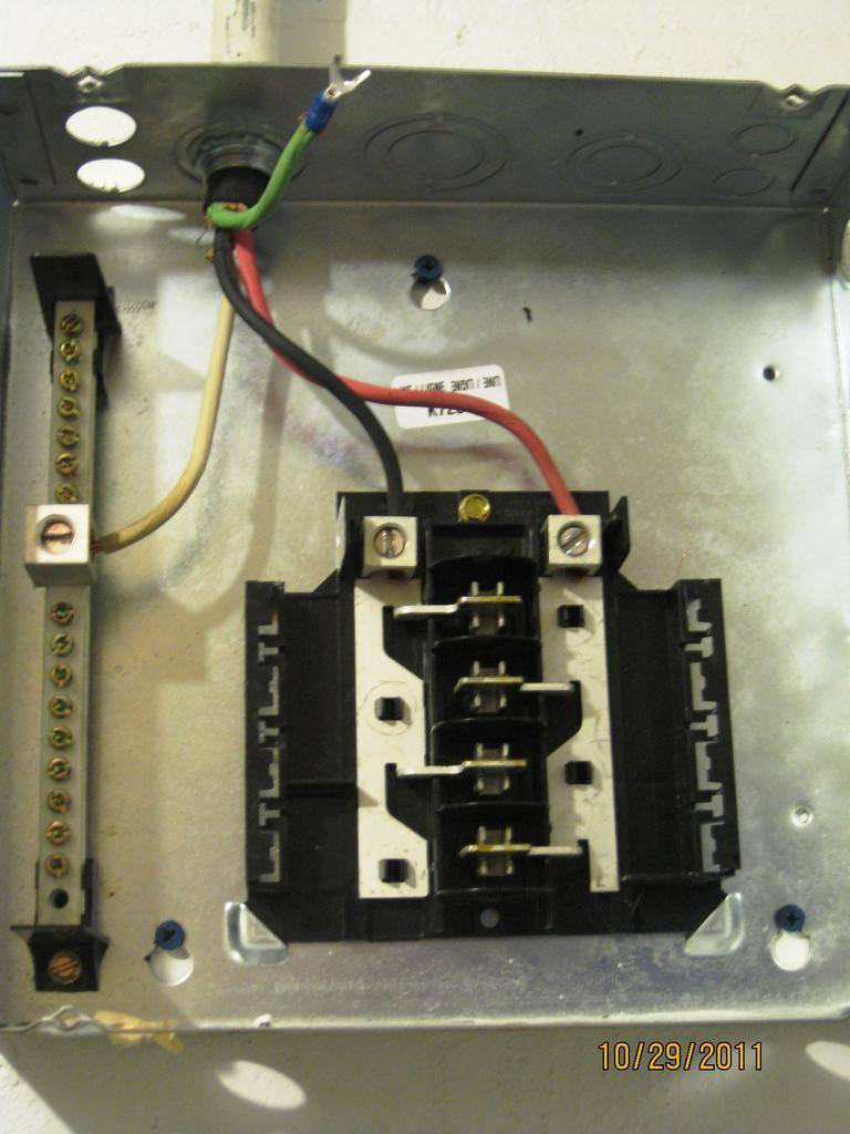
This is the Main panel with the new 60A breaker. Using 8/4 wire. Red, and Black to the breaker, white to the hot bar, and green to ground


Then to the sub panel. Black on left, Red on Right, White to the hot bar, and Green to the grounding bar I bought, and installed yesterday.


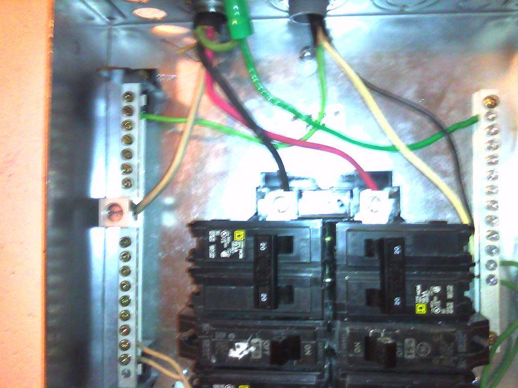
The Sub Panel with breakers installed, and switching to 14/3 wire
For the 20A 240 breaker Black, and white to the breaker, and green ground to the hot bar. The two 120 20A breakers. Black to breaker, white to hot bar, and green to ground bar.


Then to the timer from the 240 20A breaker.


This is where I get a little confused. Should the white go to 'A', or to 3 Line? Right now I have it going to 3 Line.


Will be wiring the second timer today, and installing the jacks, and the ballasts.

Wanna make sure I've got this all wired correctly before flipping the switch at the main panel.

Sorry about the last few pics. They were taken with a camera phone cuz that's all I had available at the time

So. What do you think guys?

JG
 

dominicangreen

Weed Robot
Veteran
hey bro you lost me 240v breaker to your timer should be red and black then a ground to chasy of timer.why do you have white and black wires? looks like your running 120v on timer make sure you know if timer is 220-240v or 110-120v or you will kill the timer if wrong electric is provided
 

dominicangreen

Weed Robot
Veteran
how many lights are you going to run because 1000w ballast on 240v is around 4.5-5 amps
and 1000w ballast on 120v is around 9 amps plus do math on fans and dehumitifier ac and ect. so you know how my amps you'll be using
 

rives

Inveterate Tinkerer
Mentor
ICMag Donor
Veteran
To start with, your conductor size is too light. For a 60 amp breaker, you need #6 wire, and for a 20 amp you need #12. The timer appears to wired correctly - the T104 uses the "A" terminal if you are going to drive the timer with 277v. Your hot wires (line side) go on 1 & 3, and your load wires go on 2 & 4.

*edit* Just looked more closely, I was too busy freaking out about the wire size - what you refer to as a "hot bar" is the neutral buss. The green ground wire on the 240v 20a circuit should be landed on the ground buss, not the neutral buss. Why isn't the ground wire in the main panel on the ground buss instead of attached to the side of the can? I can't tell from the pictures, but one of the screws in the neutral buss should be long enough to bond the can and the buss together. This should not be used in a sub-panel - the only place where the neutral and the grounds should be bonded together is in the main panel.
 
Last edited:

dominicangreen

Weed Robot
Veteran
right about the wire gage is why i ask what is being used..
i always run a 6/3 with 60amp braker from main pannel to sub pannel. in sub pannel i use 2-30amp brakers 10/2 wire from brakers to sepret timers and
same 10/2 from timers to the outlets ..i run 9 1000w ballast on 240v that pannel lights are 45amps in total on 240v.. i also run 120v out same sub 20amp braker for a/c and another 20amp for fans and dehumitifier still leaves me 5 amps extra to not force the 60amp in main pannel
 
Last edited:

rives

Inveterate Tinkerer
Mentor
ICMag Donor
Veteran
right about the wire gage is why i ask what is being used..
i always run a 6/3 with 60amp braker from main pannel to sub pannel. in sub pannel i use 2-30amp brakers 10/2 wire from brakers to sepret timers and
and same 10/2 from timers to the outlets ..i run 9 1000w ballast on 240v that pannel lights are 45amps in totalon 240v.. i also run 120v out same sub 20amp braker for a/c and another 20amp for fans and dehumitifier still leaves me 5 amps extra to not force the 60amp in main pannel

I see where you were going with it now. However, the breaker size is what determines the wire size (aside from voltage drop considerations), not the connected load. I don't know about the code where you are, but for the U.S. NEC you shouldn't exceed 80% of the breaker rating for a continuous load. As far as the wire color problem that you pointed out, he could handle that with some phase tape on the wire.
 

dominicangreen

Weed Robot
Veteran
I see where you were going with it now. However, the breaker size is what determines the wire size (aside from voltage drop considerations), not the connected load. I don't know about the code where you are, but for the U.S. NEC you shouldn't exceed 80% of the breaker rating for a continuous load. As far as the wire color problem that you pointed out, he could handle that with some phase tape on the wire.

your right about it all.my main pannel is in basement where its cool year round and the setup i have doent continue run all them amps because dehumitifier shuts off and on, a/c turns on and off through out the day so my amps are always up and down something a person my want to note on what their setup is like..
im no tec but been running this style setup for years and still to this day a braker has not pop on me, knock on wood lol.

great info rives,peace
 

dominicangreen

Weed Robot
Veteran
To start with, your conductor size is too light. For a 60 amp breaker, you need #6 wire, and for a 20 amp you need #12. The timer appears to wired correctly - the T104 uses the "A" terminal if you are going to drive the timer with 277v. Your hot wires (line side) go on 1 & 3, and your load wires go on 2 & 4.

*edit* Just looked more closely, I was too busy freaking out about the wire size - what you refer to as a "hot bar" is the neutral buss. The green ground wire on the 240v 20a circuit should be landed on the ground buss, not the neutral buss. Why isn't the ground wire in the main panel on the ground buss instead of attached to the side of the can? I can't tell from the pictures, but one of the screws in the neutral buss should be long enough to bond the can and the buss together. This should not be used in a sub-panel - the only place where the neutral and the grounds should be bonded together is in the main panel.

how can you see if its T104 or T103 timer in them pictures?
 

rives

Inveterate Tinkerer
Mentor
ICMag Donor
Veteran
how can you see if its T104 or T103 timer in them pictures?

In the top picture of the timer, it shows the inside of the cover enough to see that it says "250 volt". I know that the T103 is 120 volt, and the T104 is 240, so... Perhaps it is referring to the contact rating, and I'm full of shit! However, if he has the clock motor fed with 240, I'd better not be.
 

dominicangreen

Weed Robot
Veteran
In the top picture of the timer, it shows the inside of the cover enough to see that it says "250 volt". I know that the T103 is 120 volt, and the T104 is 240, so... Perhaps it is referring to the contact rating, and I'm full of shit! However, if he has the clock motor fed with 240, I'd better not be.


the shit that trips me is the wire colors on timer and that 14 gage in it is why i think they running 120v..guess he'll stop back in and explain his whole setup hopefully before something goes wrong
 

JG's Ghost

Active member
hey bro you lost me 240v breaker to your timer should be red and black then a ground to chasy of timer.why do you have white and black wires? looks like your running 120v on timer make sure you know if timer is 220-240v or 110-120v or you will kill the timer if wrong electric is provided
They are water heater timers specifically made for 240, and I've use one on 240 for several years. Just can't remember if the white wire goes to 3 line, or A.
 

JG's Ghost

Active member
To start with, your conductor size is too light. For a 60 amp breaker, you need #6 wire, and for a 20 amp you need #12. The timer appears to wired correctly - the T104 uses the "A" terminal if you are going to drive the timer with 277v. Your hot wires (line side) go on 1 & 3, and your load wires go on 2 & 4.

*edit* Just looked more closely, I was too busy freaking out about the wire size - what you refer to as a "hot bar" is the neutral buss. The green ground wire on the 240v 20a circuit should be landed on the ground buss, not the neutral buss. Why isn't the ground wire in the main panel on the ground buss instead of attached to the side of the can? I can't tell from the pictures, but one of the screws in the neutral buss should be long enough to bond the can and the buss together. This should not be used in a sub-panel - the only place where the neutral and the grounds should be bonded together is in the main panel.


Yea. I know. The pictures suck. So your saying move the green wire to the ground bar, and the rest is wired correctly. Right? The reason the green wire on the main breaker is not attached to a ground bus is because there isn't one.
Disregarding the wire size. 14/3 is what I had, and should be fine for one light I'm only going to be running one light per 20 amp breaker, and nothing else. All other equipment is being run from different circuits from the main panel

JG
 

JG's Ghost

Active member
Well, According to these the white wire goes to 3 line, Nor 'A'

If anyone has a reason they think that is wrong, please speak up.


Thanks

JG
 

rives

Inveterate Tinkerer
Mentor
ICMag Donor
Veteran
14/3 is what I had, and should be fine for one light I'm only going to be running one light per 20 amp breaker, and nothing else. All other equipment is being run from different circuits from the main panel JG

This is absolutely incorrect. If you are only going to be running one light, and want to stay with the existing wiring, go to a 15 amp breaker and a 50 amp main. The breakers are not there for when everything is running healthy - if that were the case, you could run everything off of your 200 amp main and call it good. Breakers protect you from a ground fault or a sustained overload. In the case of a ground fault, it will try and pull everything that the utility can source, limited only by the circuit impedance, until the breaker trips. A sustained overload can pull substantially more than the breaker rating for far longer than you would believe even on a brand-new, in-spec breaker. Check out the following link for the time-current curves for clearing time on new GE residential breakers. At 200% loading, it will take a minimum of 15 seconds for your breaker to trip, and a maximum of nearly 2 minutes.

In your main panel, the grounds and the neutrals can go on the same buss. I don't see any other grounds on that buss, that is why I thought that there was a separate ground buss. Is that panel even grounded? There should be at least a #6 bare ground wire in there that goes to a ground rod, and I don't see one.


http://www.geindustrial.com/publibrary/checkout/GES-6202A?TNR=Time Current Curves|GES-6202A|generic
 
Last edited:

JG's Ghost

Active member
This is absolutely incorrect. If you are only going to be running one light, and want to stay with the existing wiring, go to a 15 amp breaker and a 50 amp main. The breakers are not there for when everything is running healthy - if that were the case, you could run everything off of your 200 amp main and call it good. Breakers protect you from a ground fault or a sustained overload. In the case of a ground fault, it will try and pull everything that the utility can source, limited only by the circuit impedance, until the breaker trips. A sustained overload can pull substantially more than the breaker rating for far longer than you would believe even on a brand-new, in-spec breaker. Check out the following link for the time-current curves for clearing time on new GE residential breakers. At 200% loading, it will take a minimum of 15 seconds for your breaker to trip, and a maximum of nearly 2 minutes.

In your main panel, the grounds and the neutrals can go on the same buss. I don't see any other grounds on that buss, that is why I thought that there was a separate ground buss. Is that panel even grounded? There should be at least a #6 bare ground wire in there that goes to a ground rod, and I don't see one.


http://www.geindustrial.com/publibrary/checkout/GES-6202A?TNR=Time%20Current%20Curves|GES-6202A|generic


Look n the bottom Right corner. I appreciate the advice on what should be used, but there are (as always) money concerns involved. and 14/3 is what I had available without spending any more money. Same goes for 8/4. It was a bitch enough getting the 8/4 through the raceway that was already the . Had to take it apart, and pull the wire through a section at a time, then re assemble it. I'm not interested in running a circuit up to the max it can handle just want one that will do the job, and not burn the place down. Also I did not want to go with the existing wiring. Go to my new warewhouse build thread, and you'll see why.


JG
 
F

Fastcast

icon5.gif
I mean this in a nice way,you shouldn't be doing this if you have to ask this question!Please be careful!!!!!!!!!!!!!Get a book if you have to take the risk of doing it yourself.This shit scares me!Good luck and I do mean that!
icon4.gif
 

JG's Ghost

Active member
I've worked with this same equipment before. Just wanted to verify since it had been a while since I built a setup.

Thanks for the positive vibes though.

JG
 

rives

Inveterate Tinkerer
Mentor
ICMag Donor
Veteran
Look n the bottom Right corner. I appreciate the advice on what should be used, but there are (as always) money concerns involved. and 14/3 is what I had available without spending any more money. Same goes for 8/4. It was a bitch enough getting the 8/4 through the raceway that was already the . Had to take it apart, and pull the wire through a section at a time, then re assemble it. I'm not interested in running a circuit up to the max it can handle just want one that will do the job, and not burn the place down. Also I did not want to go with the existing wiring. Go to my new warewhouse build thread, and you'll see why.JG

Ok, I see it now. That ground should actually be landed on the neutral buss with a bonding screw tying the buss to the can. I can understand the desire to keep costs down - however, correctly-sized breakers are relatively cheap, particularly considering the potential downside. If the place does burn (noting that there are no grounds going out the other conduits), your insurance policy will likely be invalidated as a result of an installation not conforming to code.
 
Top