
johnnybsmokin
Active member
Hello all, thought it was about time a put togethers this DIY tutorial for all to read and hopefully make use of.These can be used to run the Pl-s and Pl-l type of bulbs as well a the ordinarly "fluro" tubes, just use the same size or there abouts "wattage" of the balasts to lights. So read on and by all means ask questions.
The show begins-
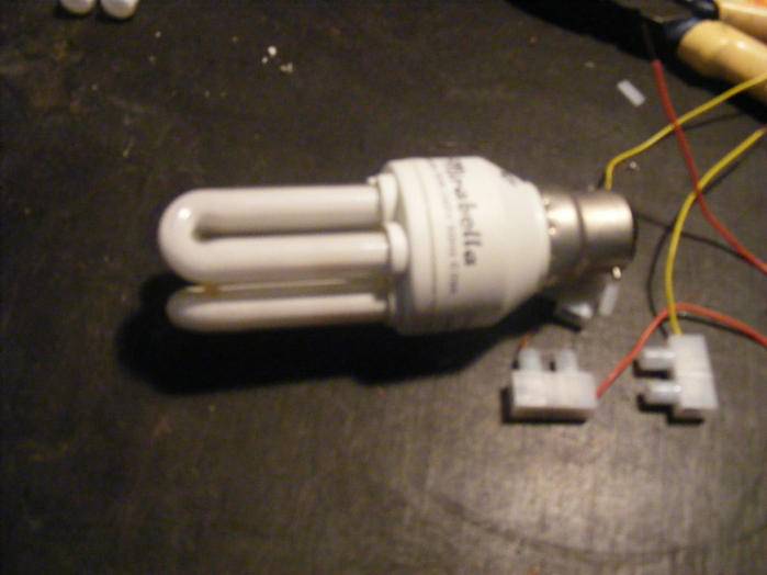
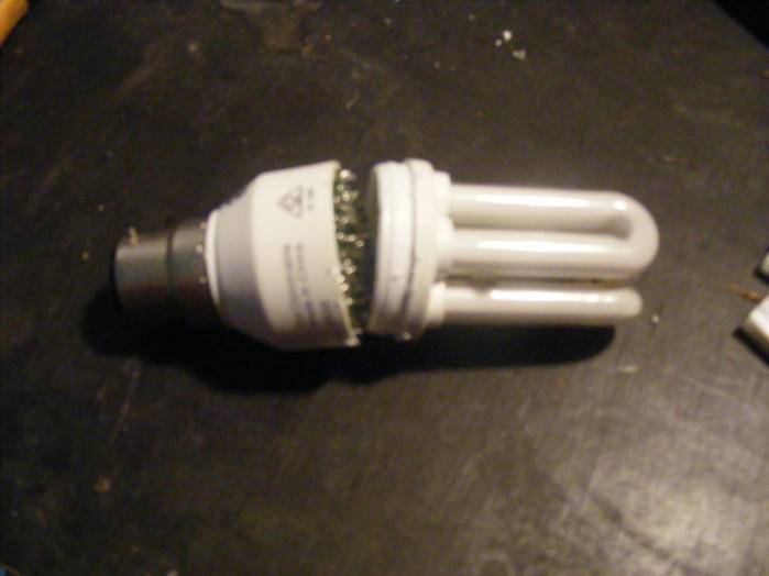
First the starting point,the bulb.In this cas I am using a burnt out/blown 10 watt CFL and will be running a 11 watt Pl-s
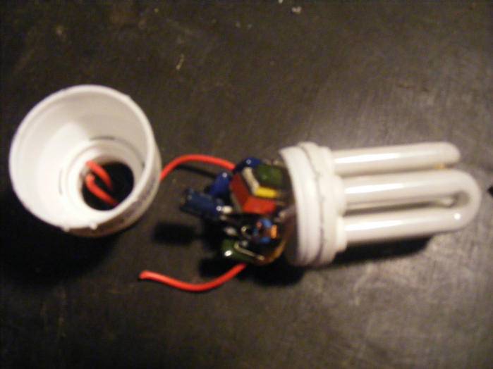
Next you will have to "pry" open the casing of the balast. This can be an easy operation ans some times a little harder. Some brands just clip together and some tend to be "glued/sealed", but usually just insert a screw driver into the "joint" and pry apart and you get the following-
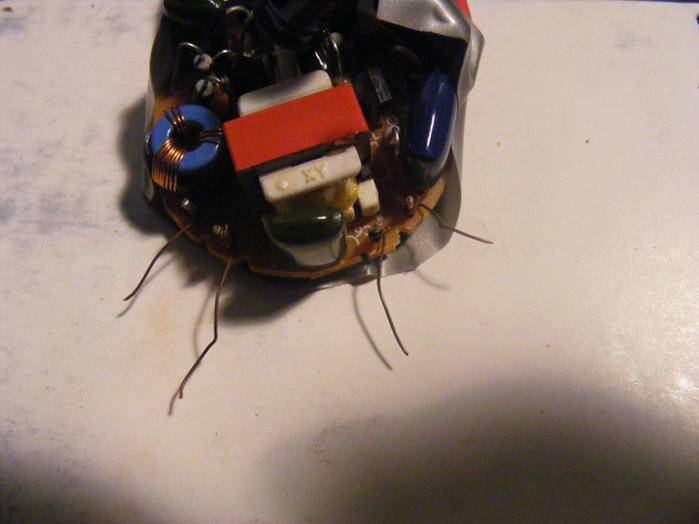
Next you have 2 options. 1/ is to cut the wires that lead to the "boyonet' or "edison" light fitting and hard wire to a power source as I have done or 2/ can be left attached and plugged into a corresponding "scocket"
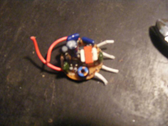
Now in the above pic you will notice that both of the wires are red, this is the first time I have found both to be red, usually they are red & black or some times brown & blue. Does not matter as conection to a power supply is simple. NOTICE it does not matter as it is AC (alternating current) but if you are concerned just join the wire to the same coloured source. If you have differnet colours to source and balast, remember the following "blue" is "cool" and brown is "active" or "hot". Now blue to black (ie cool to negative) and brown to red (hot to red (which is the colour of hot)).
The next step to "insulate the back/circuit side of the balast with duct tape" ( to avoid a shock and short circuit) and then to seperate the wires leading to the "bulb" of which there are 4 wires, 2 to each tube end as follows-
These usuall have white "protective" sleaves on them that just slip of
These wires need to be conected to the ends of the Pl type or fluro tubes similar to how they where conected to the CFL tubes. 1 pair to each end of the new light. Think of it as 2 pairs of wires, 2 wires ont the left form 1 pair and the other form the other pair. This is clearly seen in the next photo they are coloured differently and cabled tied together.
 ( the finshed product)
Next step is to join/extend the wires for connecting to your new light. I have used 2 different colours (yellow and red in this case) so as not to get confussed and I sugest you do to. Start by twisting wires together in preperation to soldering them as follows-
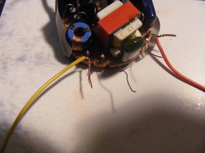
Solder together and then apply heat shrink tubing to make sure it is insulated from each other. This can be seen in the following-

Now repeat for all wires and you will end up as follows-
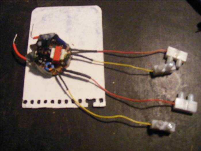
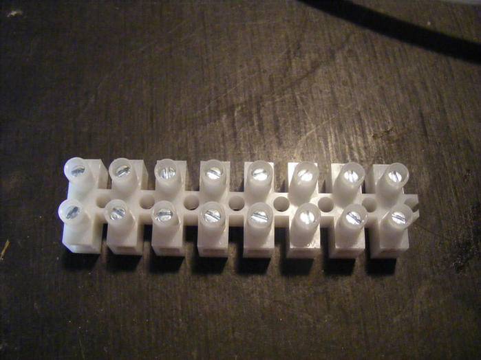
As can be seen i have already attached the "joining" blocks to the end of the wires ready for conection. For this I used the following which is a standard wireing block that is cut into individual sections with the "tags" cut off allowing them to sit close next to each other. See the next pics for explanation-
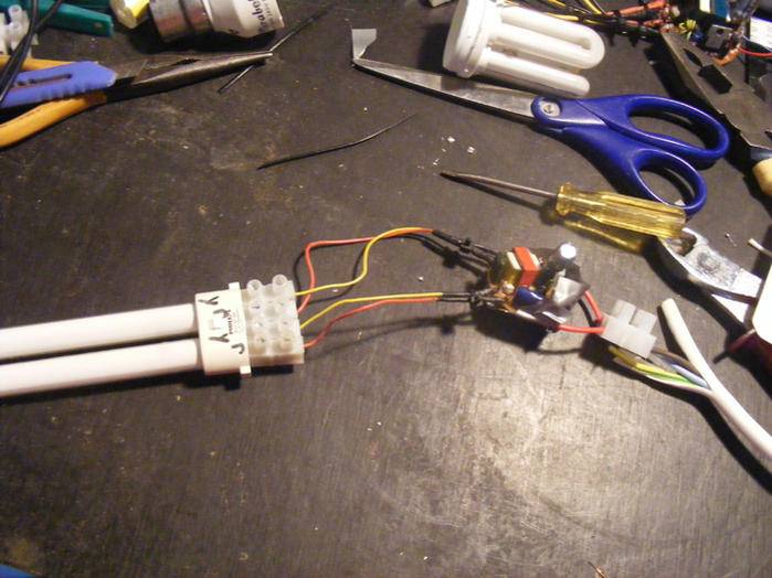
Now the final step is to connect the "blocks" to the light (Pl type or Fluro) as can be seen in the following.
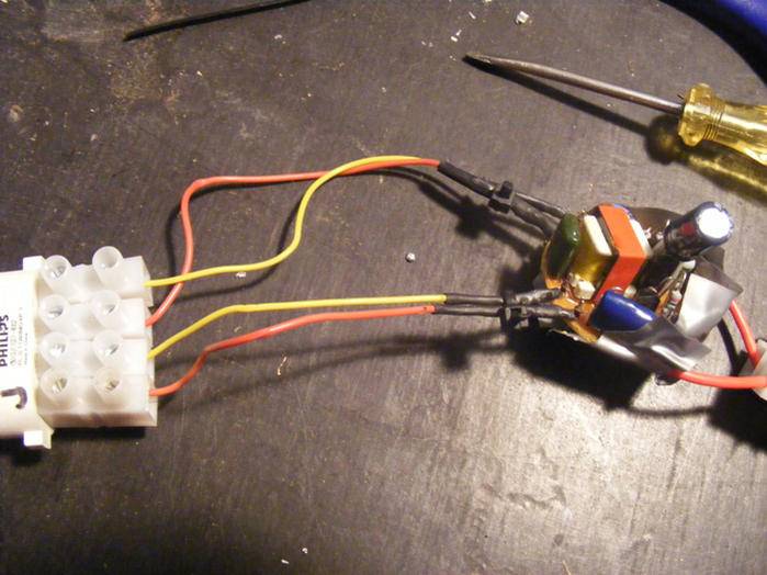
Just remember 1 pair to each end of the tube, in this case the Pl-s but the same is for the furo tubes just connect the pairs to each end and as can be seen red,yellow & red & yellow again (i just connect the coloured wires so they are the same as the corresponding end ie yellow to 1 side and the red to the other side top and bottom when looking at the fluro tube).
The result is as follows-

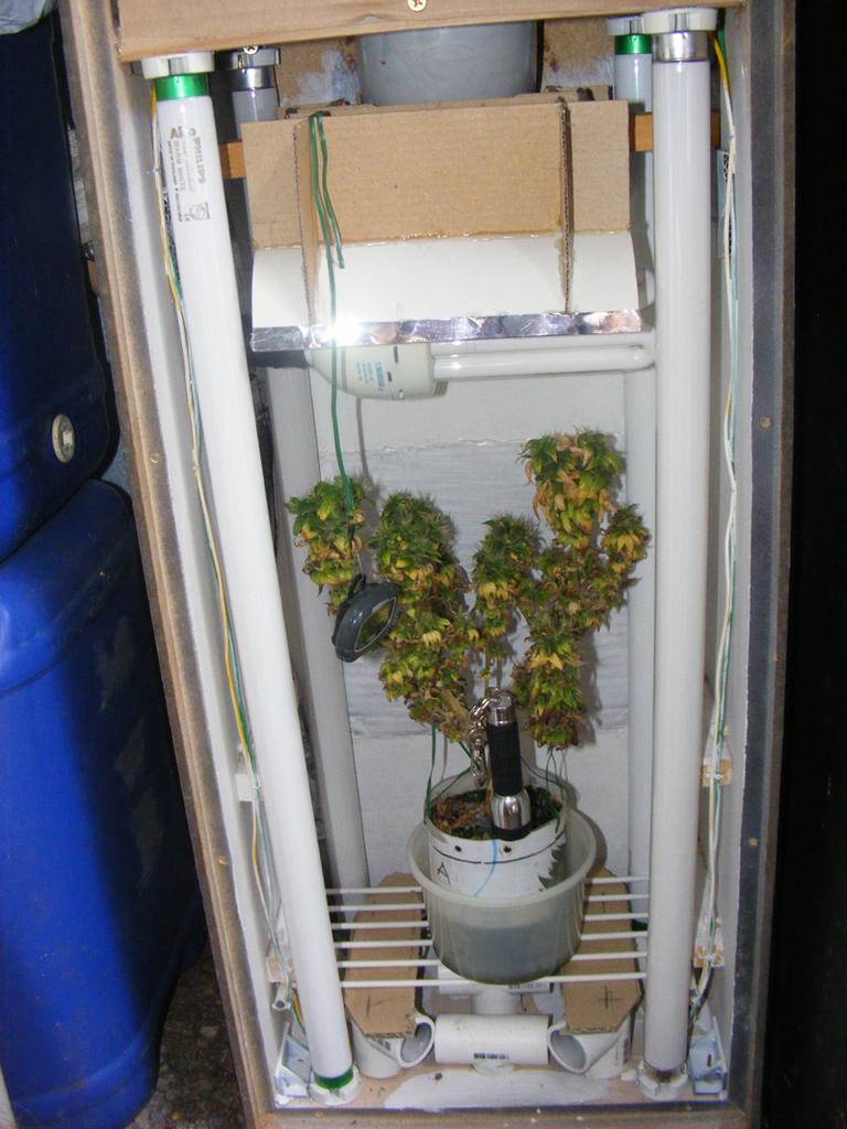
The last photo is of a speaker cab that I built to flower out my mums as they get to mature and big for my mum/veg cab. This cab is made out of a standard speaker that you find in most homes etc. It contains 4 x 2 foot fluro tubes( 2x cool white & 2x warm white) 1 in each corner and a 42 watt CFL above with a DIY "bat wing" refector. This one produced 18 grams dried but it needs some work as the heat is a bit of a problem. ( I will in time do a grow and construction report on this cab)
OK thats about it, you will find similar artical's in regard to remoteing CFL ballasts to reduce heat but I thought I would take it further. This is just my take on it and I have had great succes with it.
Just remember that you will need to insulate the "circuit" side of the balast, in my case I cut some duct tape and stick it to the "board". Filure to do this could result in a "shock" and/or frying the circuitry remember SAFETY FIRST.
Cheers Johnny
The show begins-
First the starting point,the bulb.In this cas I am using a burnt out/blown 10 watt CFL and will be running a 11 watt Pl-s
Next you will have to "pry" open the casing of the balast. This can be an easy operation ans some times a little harder. Some brands just clip together and some tend to be "glued/sealed", but usually just insert a screw driver into the "joint" and pry apart and you get the following-
Next you have 2 options. 1/ is to cut the wires that lead to the "boyonet' or "edison" light fitting and hard wire to a power source as I have done or 2/ can be left attached and plugged into a corresponding "scocket"
Now in the above pic you will notice that both of the wires are red, this is the first time I have found both to be red, usually they are red & black or some times brown & blue. Does not matter as conection to a power supply is simple. NOTICE it does not matter as it is AC (alternating current) but if you are concerned just join the wire to the same coloured source. If you have differnet colours to source and balast, remember the following "blue" is "cool" and brown is "active" or "hot". Now blue to black (ie cool to negative) and brown to red (hot to red (which is the colour of hot)).
The next step to "insulate the back/circuit side of the balast with duct tape" ( to avoid a shock and short circuit) and then to seperate the wires leading to the "bulb" of which there are 4 wires, 2 to each tube end as follows-
These usuall have white "protective" sleaves on them that just slip of
These wires need to be conected to the ends of the Pl type or fluro tubes similar to how they where conected to the CFL tubes. 1 pair to each end of the new light. Think of it as 2 pairs of wires, 2 wires ont the left form 1 pair and the other form the other pair. This is clearly seen in the next photo they are coloured differently and cabled tied together.
Next step is to join/extend the wires for connecting to your new light. I have used 2 different colours (yellow and red in this case) so as not to get confussed and I sugest you do to. Start by twisting wires together in preperation to soldering them as follows-
Solder together and then apply heat shrink tubing to make sure it is insulated from each other. This can be seen in the following-
Now repeat for all wires and you will end up as follows-
As can be seen i have already attached the "joining" blocks to the end of the wires ready for conection. For this I used the following which is a standard wireing block that is cut into individual sections with the "tags" cut off allowing them to sit close next to each other. See the next pics for explanation-
Now the final step is to connect the "blocks" to the light (Pl type or Fluro) as can be seen in the following.
Just remember 1 pair to each end of the tube, in this case the Pl-s but the same is for the furo tubes just connect the pairs to each end and as can be seen red,yellow & red & yellow again (i just connect the coloured wires so they are the same as the corresponding end ie yellow to 1 side and the red to the other side top and bottom when looking at the fluro tube).
The result is as follows-
The last photo is of a speaker cab that I built to flower out my mums as they get to mature and big for my mum/veg cab. This cab is made out of a standard speaker that you find in most homes etc. It contains 4 x 2 foot fluro tubes( 2x cool white & 2x warm white) 1 in each corner and a 42 watt CFL above with a DIY "bat wing" refector. This one produced 18 grams dried but it needs some work as the heat is a bit of a problem. ( I will in time do a grow and construction report on this cab)
OK thats about it, you will find similar artical's in regard to remoteing CFL ballasts to reduce heat but I thought I would take it further. This is just my take on it and I have had great succes with it.
Just remember that you will need to insulate the "circuit" side of the balast, in my case I cut some duct tape and stick it to the "board". Filure to do this could result in a "shock" and/or frying the circuitry remember SAFETY FIRST.
Cheers Johnny


