What's new

Home-grown RH & temp controller

Mulletsoda

Member
I'm designing a humidity / temp controller, and I thought I'd post up some pics and thoughts as the build unfolds. The situation here is the main adjustor is an exhaust fan which brings air in from a crawlspace type area. For the purposes of this design, I'm assuming the intake air is always going to be cool enough to bring the room temp down. However, the RH in there may be too high at times to bring the level in the room down, so there is a backup dehumidifier. It seems real simple, and it is, but outlining each step has proved to be a bigger task than I had thought.

At the moment I'm more concentrating on the logic behind it. Here are a few of my thoughts, things I feel need to be addressed in it's operation:

* When the vent is activated, I don't want it to turn back off right away. ( Example : if the sensor gets placed in the path of incoming air, as soon as it kicks it on, it will immediately register acceptable values again. ) A minimum on time will help prevent appliance cycling.

* I was thinking of an adjustable 'swing' amount for each value. ( Example : if your goal is 75 degrees, no swing would mean that 76.0 kicks it on and 75.9 (or 75.0) turns it back off. ) Depending on the size of the room being cooled, the room's ability to hold heat, the placement of the sensor and other factors, it may prove more efficient to activate your appliances less frequently.

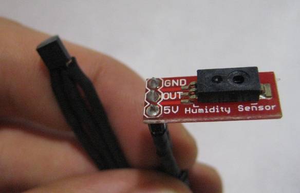
* There will be a secondary RH sensor placed in the area where the intake draws it's air from to help the controller decide to use the vent or the dehumidifier.

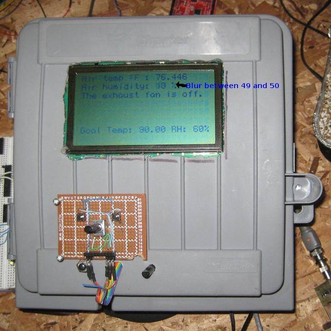
* There will be the obvious things : an adjustable goal for temp, an adjustable goal for RH, a display (probably an 8x24 charactor LCD, just because I have it already), some sort of interface hardware (buttons and a knob), and a place to tie in electrical circuitry. This project is being done for an electrician (Yea!!) so I don't have to put outlets or any fancy packaging like that, he's going to wire his shit right to it.

Some other possible features I might put in :
* Timed outlet, depending on available memory and I/O pins
* Some sort of logging... maybe % of time ON over the last 12/24 hours
* Fault detection... if the vent is no longer having an effect, signal an alarm
* Saving settings to EEPROM (this will make your settings stay after the unit loses power)

picture.php


picture.php
 

Mulletsoda

Member
If anybody's interested in the code, I can post that no problem. It's definitely a work in progress, keep in mind! The actual hardware I've got in here at the moment is :

* Atmega168P20, programmed with an arduino (shoutout to http://arduino.cc !) then slapped onto a breadboard.
* 8x24 LCD, from PJRC
* DS18B20 temp sensor, a 9-bit OneWire sensor from Maxim
* HIH-4030 RH sensor, mounted on a breakout board from SparkFun
* Housebox for outside wire connections ( I love re-purposing things )
* Misc nonsense... breadboard, voltage regulator, headers, buttons... lots of Cat-5 wire
* Cat-5 female piece to make connecting main box to it's relays easier
 
T

tokinafaty420

wow that is cool. This is a first for me to see someone actually make their own controller.
 

Mulletsoda

Member
I have yet to quite get there... I'm definitely on the road, though! I've got a whole room controller plan in the works right now, I've been working on it for about 6 months. It's intense, turned into a really big project. I didn't know jack about electronics before I started this, so if anybody needs inspiration or a little push to start learning... I'm completely self taught and my budget reflects my unemployed status. So there's no excuse!
 

dybert

Active member
This is really cool I'd love to do something like this.... What did you write the code in? (I have a CS degree if you want any help or anything )
 

Mulletsoda

Member
I think it's very similar to C++, at the moment I use the Arduino IDE. It's very basic, if you've ever done programming this wouldn't present any problems. I did some VB work in high school (10 years ago!) and nothing since, and I picked this up after about a week. The arduino IDE wraps up the technical parts of uploading firmware to the chip, I've never done direct port addressing, never had to compile my own code, hell, I upload using USB, takes about a minute. Here's a sample, just open as a text file : http://mulletsoda.is-a-geek.org/atmega/sample_RHtemp.pde Here's a reference sheet, almost every command used is on this short list : http://arduino.cc/en/Reference/Extended

I'd love any help you can give, not sure what that would be at the moment, though. I'm doing this as an open-source project, so really, the best thing I could think of would be for you to take what I've done and adapt it to your own needs and circumstances and publish how you did that. I really need to get on my documentation, I tinker around with this stuff almost every day. All thoughts, criticisms, any sort of input would be appreciated.
 

Mulletsoda

Member
picture.php


Here's a pic of the insides. This part is finished, there is another piece that goes with it on the other side of that Cat-5 cable. This is low voltage only, I try to keep the high voltage away from the logic voltage. The 12V signals from this box will trigger relays in another box, which will do the actual controlling of appliances. That ethernet port there carries 4 signal wires and 12V power for the remote board.
 

Mulletsoda

Member
Alrighty... so I finally finished this one. Here's a link to the product manual I provided with it : http://rhtempcontroller.googlecode.com/files/RH Temp Controller.pdf. There are a bunch of pictures illustrating everything in there, as well as written descriptions. The source code is also hosted on Google code if anybody is interested. Any questions, let 'em rip!

img7454p.jpg


I think the total cost came to around $150 or so... I kinda felt like that was high, but whatever, it's cheaper than commercially available options. :D Anybody want instructions on building one? I guess I could write up a schematic. I made this for someone with an understanding of electricity, that's why no outlets. Those relays in there are 12A220V ice cube style with .25" QC tabs.

img7405y.jpg
 
Last edited:

ChaosNyx

Member
Very cool project! So it cost a little more than you wanted ,It is still cheaper than off the shelf.
I haven't messed with programing and code since tech school. 20 years ago:laughing:. I could not even remember basic!!LOL Can't wait to hear how it works.
ChaosNyx
 

Mulletsoda

Member
Very cool project! So it cost a little more than you wanted ,It is still cheaper than off the shelf.
I haven't messed with programing and code since tech school. 20 years ago:laughing:. I could not even remember basic!!LOL Can't wait to hear how it works.
ChaosNyx

I can't wait to hear how it works either... :whee: :whee: :whee: I tinkered it together over about a month and gave it two days of in house testing before I handed it over. It worked as far as I could tell: when I breathed on the RH sensor or held the temp probe it activated the relay, and the timer's relay clicked it's merry way too. We'll see how it performs in the real world. My basic controller has worked for many months without any hiccups, so I have a good amount of confidence in this one.
 

cannabi

Member
Hey Mulletsoda, is there any way to use your controller to read a door jamb button to turn off an LED lamp and turn on a couple CFL bulbs in the cabinet when the door opens so that when the door is open the grower observes his plants under regular lighting and when the doors are closed the CFLs shut off and the LED light turns back on?

Edit: Also, can it keep track of night and day and gradually alter the day/night cycle to start at 20/4 and slowly creep into 12/12 as the actual season would? And when the doors are open during the night cycle can it activate a green bulb via the same door jamb switch?
 

Mulletsoda

Member
Hey Mulletsoda, is there any way to use your controller to read a door jamb button to turn off an LED lamp and turn on a couple CFL bulbs in the cabinet when the door opens so that when the door is open the grower observes his plants under regular lighting and when the doors are closed the CFLs shut off and the LED light turns back on?
Yes, but why would you want to? Are you referring to LED grow lights? My LED lighting is all green so I can go in during the dark photoperiod, there is no point on them being on when nobody is around.
Edit: Also, can it keep track of night and day and gradually alter the day/night cycle to start at 20/4 and slowly creep into 12/12 as the actual season would? And when the doors are open during the night cycle can it activate a green bulb via the same door jamb switch?
Absolutely.
 

cannabi

Member
I just want to be able to shut off a LED Grow Light automatically during the lights on cycle while having a lower wattage CFL bulb or two come on when the LED lights shut off so that my entire room doesn't glow purple when the cabinet doors are open. I'd also like to observe the plants under normal lighting when I open the doors.
 
B

BlackThumb

Hey MS,

I missed this project. I have been following your PH/TDS dosser.

Have you had a chance to try rolling your own PCB?
I am doing one right now for a prototype remote CO2/Temp/Light/Humidity sensor that can plugged into my current standalone CO2 controller.

I have had a number of requests for a remote (cabled) option.
Not sure why but people seem to want it. <shrug>

Looks great. I love the LCD, makes my 20 x 4 look downright lame.

Peace,
-BT
 

Mulletsoda

Member
No, I haven't got myself a laser printer yet, so no PCBs. It is on the list, though.

I started this project before the pH one. ;-) I'm real slow at times, but it'll get done eventually.
 
Top