What's new
  • Happy Birthday ICMag! Been 20 years since Gypsy Nirvana created the forum! We are celebrating with a 4/20 Giveaway and by launching a new Patreon tier called "420club". You can read more here.
  • Important notice: ICMag's T.O.U. has been updated. Please review it here. For your convenience, it is also available in the main forum menu, under 'Quick Links"!

Growroom Electricity and Wiring

Hemphrey Bogart

Active member
Veteran
I'm a little confused as to your question.

If you actually have a dedicated grounding bus bar in your panel that is mounted right against the steel of the panel enclosure, then you must terminate all bare (or green) grounds to that only. Then you'll have one or two neutral bus bars that are lifted up a tad and sit on some black plastic so they don't touch the metal of the panel. All neutrals need to be terminated to that.

If thats the case, then you have a separate disconnect somewhere else, probably outside by your meter.

Let me know if it misunderstood anything. I am pretty high on opiates right now.... :blowbubbles:

I don't have a dedicated grounding bar in the panel. The ground wire runs from the earth ground to the panel.
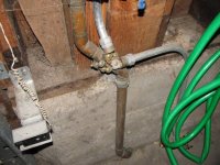
IMG_1722.JPG

That wire is attached to the main box, no ground bar:
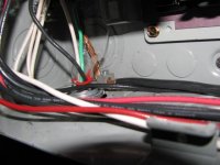
IMG_1735.JPG

Then, then it gets terminated to the neutral bar:
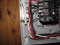
IMG_1737.JPG

The panel:

IMG_1728.JPG

I'm using 12/2 SMC cable. I think I can add a couple 15 amp breakers for fans and low load stuff, yes?

Thanks MP.
 

madpenguin

Member
MP...
thanks again for the answers i really appreciate it...

so what i ended up doing... I bought the intermatic t103 and ran 12/2 romex from a jbox under my power board to a dbl gang box, and here i added 2- 120v 20a duplex receptacles, i also pigtailed power going to timer... from timer i go into other dbl gang box and added 2 more 120v 20a duplex receptacles which will be timer controlled... i just used 12/2 romex to go from box to box and timers so i'm sure its not up to code but i'm not planning an inspection neways :) i posted pics so if anything looks dangerous or out of place to you please, by all means, slap me...

so all in all on this 20a circtuit I have 4 timer controlled recep (for only 1-600w now but will be 2x600w soon), also have the four unswitched outlets now mounted to panel as well... I also have another 20a circuit that i pulled from an unused b/r, and am going to add 4x more unswitched recep to my panel from this circuit...

man, this thread really kicks ass and i've learned more on ic in the past week than another pot board in a year... thanks a lot for helping everyone, enjoy them narcos u deserve them...

There is nothing against code with the way you ran your feed up from the floor and through the boxes. You may have to derate because of it but since it's romex you start at 90 degree celcius. Suffice it to say it would not derate the wire to under 20A so it's no big deal the way you ran it.

The wiremold looks nice and protects the feeder. Timer is hooked up correct. Also has room for another 120v circuit in there if you wanted. I really wish intermatic would use a red conductor on terminal #2 for the clock hot tho.... ;)

I would have used 2 short pieces of EMT from the timer box down to the 4x4. Or atleast PVC. Just becareful of that exposed #12.

Looks like your using #14 AC extension cords so that good. No wimpy ones. Looks good. You might want to wap all your receptacles with electrical tape. That or make sure you push the grounds all the way back into the bottom of the box. Don't want those anywhere near a neutral or hot.

But yea.... Looks nice, orderly and clean.:yay:
 

madpenguin

Member
@ Bogart... That 100A DP breaker... That is backfed with atleast #2 AL correct?

Is there another main disconnect anywhere? That's looking like a subpanel because it's a MLO loadcenter but you have your primary ground hooked up to it (the black one that goes down to the water inlet pipe.

I'd also like to see where those red wires go. Are there 2 14/3 cables entering in the right hand side that I can't see and thats where the 2 red wires are coming from?

Does that black thick wire that's acting as the main ground wire lead to the water inlet?

Lots of questions but try to answer everyone of them.

I would say that this is more than likely your main panel. That black sheathed #4 or #6 attaching to the frame first and then terminating to the neutral bus is indicative of bonding in a main breaker panel....

Is that neutral bus bar raised up off the frame of the panel or is it directly fastened to the frame of the panel just like that first grounding lug?
 

Hemphrey Bogart

Active member
Veteran
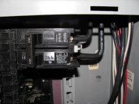
That 100A DP breaker... That is backfed with atleast #2 AL correct?

Yes, I believe so. Here's a pic...

IMG_1742.JPG

Is there another main disconnect anywhere?

Not that I know of.
The meter is right above the breakers and is all part of the same main panel.

That's looking like a subpanel because it's a MLO loadcenter but you have your primary ground hooked up to it (the black one that goes down to the water inlet pipe.

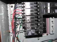
I'd also like to see where those red wires go. Are there 2 14/3 cables entering in the right hand side that I can't see and thats where the 2 red wires are coming from?

Not sure where the red wires go, they are more than likely ran to a junction box that is above the main service panel.

Does that black thick wire that's acting as the main ground wire lead to the water inlet?

Yes it does.

I would say that this is more than likely your main panel. That black sheathed #4 or #6 attaching to the frame first and then terminating to the neutral bus is indicative of bonding in a main breaker panel....

Is that neutral bus bar raised up off the frame of the panel or is it directly fastened to the frame of the panel just like that first grounding lug?

The neutral bus is raised up off the frame, not sure why the ground is termed to the panel though. This main service panel was installed and inspected back in 2000 and passed, so I figure it must be correct.
 

Hemphrey Bogart

Active member
Veteran
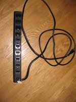
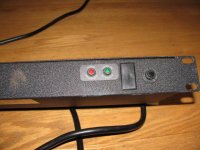
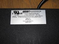
Hey MP, another quick question for you. I know you said surge suppressors aren't ideal, but can I use this for my fans?

Back: IMG_1758.JPG

Front: IMG_1755.JPG

Label: IMG_1752.JPG

I was going to plug this into a dedicated 15 amp circuit on a separate timer and run my fans off of it (maybe 3 or 4 fans total). I believe it is made for computer server rack mounts, so I should be able to mount it set off from the wall or the ceiling with some brackets. That's a 14awg wire coming off of it.
 

Luv2gro

New member
MP...
Thanks for reply... I did push grounds back but whn u say tape recep do you
Just mean taping over screws where connections are made?? Sorry not familiar
With this practice.. also will b using more molding or something from timer to box... thnks again...
 

madpenguin

Member
MP...
Thanks for reply... I did push grounds back but whn u say tape recep do you
Just mean taping over screws where connections are made?? Sorry not familiar
With this practice.. also will b using more molding or something from timer to box... thnks again...

Yea, just wrap electrical tape all the way around the receptacle so both hot and neutral terminals are covered.
 

madpenguin

Member
Hey MP, another quick question for you. I know you said surge suppressors aren't ideal, but can I use this for my fans?

I was going to plug this into a dedicated 15 amp circuit on a separate timer and run my fans off of it (maybe 3 or 4 fans total). I believe it is made for computer server rack mounts, so I should be able to mount it set off from the wall or the ceiling with some brackets. That's a 14awg wire coming off of it.

Yea. Thats fine. looks to be a well made one.
 

madpenguin

Member
Not sure where the red wires go, they are more than likely ran to a junction box that is above the main service panel.

I ask because it looks like 2 MWBC's stabbed onto tandem breakers... Which you cannot do.

The neutral bus is raised up off the frame, not sure why the ground is termed to the panel though. This main service panel was installed and inspected back in 2000 and passed, so I figure it must be correct.
Yea, that's fine. On a main panel you need to bond the neutral bus to the frame of the panel and that's exactly what that ground wire does (along with providing a primary ground).

It all looks good to me except for possibly those 2 red wires. If each one of those red wires are part of a cable assembly that also has a black and white wire, then those cable runs need to e on double pole breakers and not tandems.
 
D

Deaner

I simply cannot hire a electrician, there's no I can explain why I need all that electricity to this particular room. I pretty much bought everything I need, except I need to return a 50amp circuit because I thought I could use it with my gauge wire... I recently found out I need the 20amp circuit with the 12 gauge (dumby Lowes electric guy ).

So, this is what I got goin:

Grow room in a basement (25' away from breaker box) that will have 2 x 600 watt digis that are 120v for flowering.. In the same area my veg box with 1 x 400 watt HPS and 2 x 150 watt CFL. Plus, there will be 2 x S&P Duct fans and 1 x Dayton Blower.. not sure of their exact size but they are all under 300 cfm. Plus a couple 6" fans and a 10" fan or so. I should mention that the veg will be on a timer for 18/6.

So, I have 250' of 12gauge-3 Romex (plenty) wire. The plan is to wire them to 2 x 20amp circuits. From there, they will goto individual 2 x 4" x 4" metal boxes with 4 x GFCI outlets (in total). (such as one 12 guage wire to one 4" x 4" box... each having 4 places to plug in... now that I'm writing this, I will probably need another 4" x 4" box pig tailed since I need atleast 11 plugs.

What is my ideal setup for the equipment? I have a heavy duty 2 outlet timer that I would like to use for the 600's. Do you have any advise or criticisms? Anything I'm overlooking?

Also, I read though alot of the Electricity Sticky and confused. It sounds like madpenguin tells use when wiring the circuit that we "terminate" the ground wire before attaching the hots? Can you clarify how to wire the actual circuit without getting kills?

Thank you guys!!
 

Hemphrey Bogart

Active member
Veteran
Got any pics, Deaner? I'm not the expert here, but I think it helps MP diagnose possible problems, etc. Start with your main service panel and then maybe you can show all the gear you're trying to hook up (timer, outlets, wire, tools). Some outlet boxes have the little raised part on the inside for the ground and I think that's the best for what you're trying to do.

I think by terminating the ground wire first, you are helping to keep yourself from getting shocked unnecessarily. You can still shock yourself, but I think the idea is to minimize the chance of that happening.

From what I can gather: electricity, like water, flows along the path of least resistance. That path can be an earth ground or YOU. I prefer the ground myself.
 

Luv2gro

New member
well guys just when you think everything is going your way, boom, it doesn't, lol...

so i went in my room tonight and my fan speed control is no longer controlling fan, just simply passing 120v straight through... this fsc was wired in parallel with thermostat which allowed me to have fan running at low speed all night to keep neg pressure, then bump fan to 100% when reaching 75...

dont have an extra fsc so i ran a timer in parallel to replace fsc, my question is this mp or anyone else with knowledge, will it hurt this cheapo timer to be backfed with 120v?? because the way it works out, when tstat kicks the fan on the timer is actually being back fed 120v to its female plug... is this going to be a problem??? could this possible be why the fsc quit so soon (4 weeks appx)..

if anybody know the answers here please let me know, not to rush but its kinda a hurry, i'm leaving tomorrow for all day and don't want to come home to any surprises... thanks a lot...
 

Luv2gro

New member
ok so i know that i can't rush nebody on here cuz it's not like people are sitting and watching this thread... I know tht MP spends a lot of time answering questions and needs a break for his own grow once in a while...

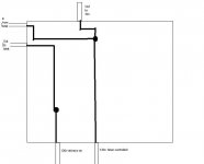
MP, i'll try to explain in more detail what i have going on in order for you to be able to help when you do get back on... also posted a drawing from paint to explain a little further, all wiring is 14g ext cord but i only diagram ungrounded conductor as neutral and gr all tie together in jbox...

1)I have 2 14g extension cords running into j box, one is hooked to cheap dig timer, one hooked to straight 120v, they are both on same circuit, so same phase etc...

2)from the always hot cable i go out to t stat (located in tent) and back into jbox

3)from cable coming back from tstat i tie black into the black from timed 120v feed cable and also tie these into black going out to fan...
4)all whites are tied together in j box

5)all gr are tied together in j box

i imagine this is a little hard to understand, as i'm not the best at explaining things in writing them lol... but basically it is set up (hopefully) to where all nite long when temps are low (67-70) the timer will kick fan on once every hour for about 10-20 min... during the day the timer is off and the t stat will kick on when temps reach 74 or so, most days the fan will run nonstop for these 12hrs.. so, the timer will actually be being fed 120v from the wrong side of the switch anytime the tstat is kicked on... i'm assuming this will not be an issue but want to make damn sure b4 i do something dumb and burn the whole house down over a lil ventilation...

if this is still unclear (sure it is) lemme know what else you need to know... thnx...
 

Attachments

  • timer wiring.jpg
    timer wiring.jpg
    13.6 KB · Views: 20

Bud-Boy

Active member
Veteran
NO access to load center can I splice my...

NO access to load center can I splice my...

No access above,
-the roof comes at too low an angle. Cant get with in three feet of the edge
No wall access
- it is set in to the exterior wall and is my kitchen on the other side
No below access
- Just isnt available.
SO
I found my dryer, 10-3-G, (double pole 30amp breaker)cable going up, across and down the attic.
can I de energize the circut, remove the breakers for safety,
cut the cable and piggy back my 12/3 in a juction box into that circut?
And
NOT run the dryer during flower hours?
 

Luv2gro

New member
bud boy...
i'm not an expert obv... i believe that while this would technically work, it is a BAD idea b/c you end up having 12/3 wire, which is rated for 20a being protected by the 30a breaker...
I think you would be ok doing this if you use 10/3 from your jbox to your room, but you'd have to make damn sure not to use dryer during hours of lights on, it would throw breaker for sure if so...
also, i'm not sure this would even be up to code if this you did it like this, that'd be a question that mp would have to answer... but i'm sure you could make it happen somehow, just gonna need to use 10/3 in order to have a 30a breaker...

is there anyway that you can just tap into an unused, or lightly used 120v circuit in the same attic?? that is what i did, i use the circuit from the growroom as well as another very lightly used 20a circuit from another room...
 

Bud-Boy

Active member
Veteran
I know it wont be up to code
not worried about that, only safety really.

Because of the access situation, all the original wiring is junctioned like crazy up there. no "lightly" used 20amp (Idont think:thinking:)

I have the room running on a dedicated 20amp breaker feeding 12-3-g yellow romex running outside the box, (fully improperly) up the exterior wall, under the roof overhang and into the grow area. the entire setup runs at less than 15 amps even at a/c kick on to cool. (as read by "kill o watt"meter)
2- 6's
a 5k btu a/c
3 fans
co2 controller
10 inch inline filter/fan
I'd like that on one half the 240v feeds up in the attic
the other side the 240v will be dedicated for 1k lamp ,an extra 5k btu A/C, 2 wall fans. -OR- 2 more 6's instead of the thouie.

Nothing else.
Im even probably going to run the 12-3 circut if I can piggy it, to a small box on 20amp breakers, then out to the room recepticals


If it gets more, I'll dedicate the current dryer circut and air dry the clothes. Get one of those 50amp plug n play, 4k lights 10amp peripherals, boxes.
 

manitu

Member
get an electrician to wire the circuits you need , but in another room , nearby.
just extend the cables into your growroom , yourself.
If you get a wall outlet on the outside of your room , you could have a spotlight or similar plugged in , just to see the status of the circuit without entering the room.
And wiring it into your growroom would be easy - just drilling trough the wall , and putting up a wall outlet on the inside.

just my two cents..
manitu
 

madpenguin

Member
From what I can gather: electricity, like water, flows along the path of least resistance. That path can be an earth ground or YOU. I prefer the ground myself.

Exactly. By hooking up the ground first, you give current a low impedance path back to the panel to facilitate the tripping of the breaker.

The breaker has to get an inrush of current before it'll trip. If most of it is going through you, then the breaker is not likely to trip and you will just electrocute yourself.

BTW, when a fault occurs, you can get upwards to 5,000 amps flowing on that wire. I certainly wouldn't want to get in the way of that. Give it a ground wire to travel on and you'll more than likely just get bit by it instead of being killed by it.
 

madpenguin

Member
Bud-Boy, that's a tap with what you are wanting to do. If your going to use that 30A circuit, you need to hit both phases and the neutral to bring down into your grow room. Then, yes, fuse both legs at 20A. Then you'll have 2 - 20A circuits which will be a MWBC. Distribute the load evenly between both phases.

I'm not a big fan of doing that but if your going to do it, then just make sure you fuse both legs coming into the room.

Get an AC disconnect box that takes the fuse cartridges. Put 20A ones in there and not 30 or 40 ones that may or may not come with it.

And yea... Watch when you run your dryer or the 30A main will throw in the panel. I also don't think I need to tell you to make sure this circuit is turned off before you start working on it...... Hopefully there is enough slack in the attic to where you can put in a 4x4 junction box and still have a few inches of both #10 conductors sticking out the front after you cut it. Use a pair of linemans pliers to mechanically twist the 2 - #10's and a #12 together. Make sure they wrap around each other really well, then use a blue wirenut to cap it.

A 12/3 run is what you would want to run into the junction box with the #10's. Just remember to even distribute the load between the red and black #12 wires and definitely fuse them.
 

madpenguin

Member
will it hurt this cheapo timer to be backfed with 120v?? because the way it works out, when tstat kicks the fan on the timer is actually being back fed 120v to its female plug... is this going to be a problem??? could this possible be why the fsc quit so soon (4 weeks appx)..


That's an interesting scenario. I'm having a hard time answering but maybe because it 5 in the AM... I'd say yes, that's why your fan controller quit working. There is one sure way to find out..... If your timer goes south then you have your answer...... ;) Altho I think a variac or triac would be MUCH MUCH more susceptible than a timer would in that instance.

I want to say that it shouldn't hurt it but fuck.... It could. There is a "line" and a "load" for a reason with devices like that....
 

Latest posts

Latest posts

Top