
touchofgrey
Active member
I’ve seen several threads where people are wondering how to build air-cooled hoods so I thought I’d do a how to on the one I just finished. I won’t say it’s a simple project that anyone could do but it’s not as hard as you might think.
I actually started out planning to build a simple bake-a-round cool tube for a new small cabinet. Then I realized the bulb really needed to be perpendicular to the long wall of my box for maximum efficiency. Didn’t have room to do that with the cool tube so the need for an air-cooled hood developed.
 I drew up a design that filled the space I had to work with and spread the light to the growing zone.
[edit see next post for drawing]
The next step was to create a flattened drawing for a cutting template. If you cut a section through a sheet metal fabrication in 2 directions there will always be a true dimension for each plane in one of those sections. Draw each plane in true size to cerate templates to cut the sheet metal shapes needed to fold up into the hood pieces. You will need to add tabs where the pieces join to make the attachment. I also added a length to fold at the edges to give a double thickness hemmed edge.
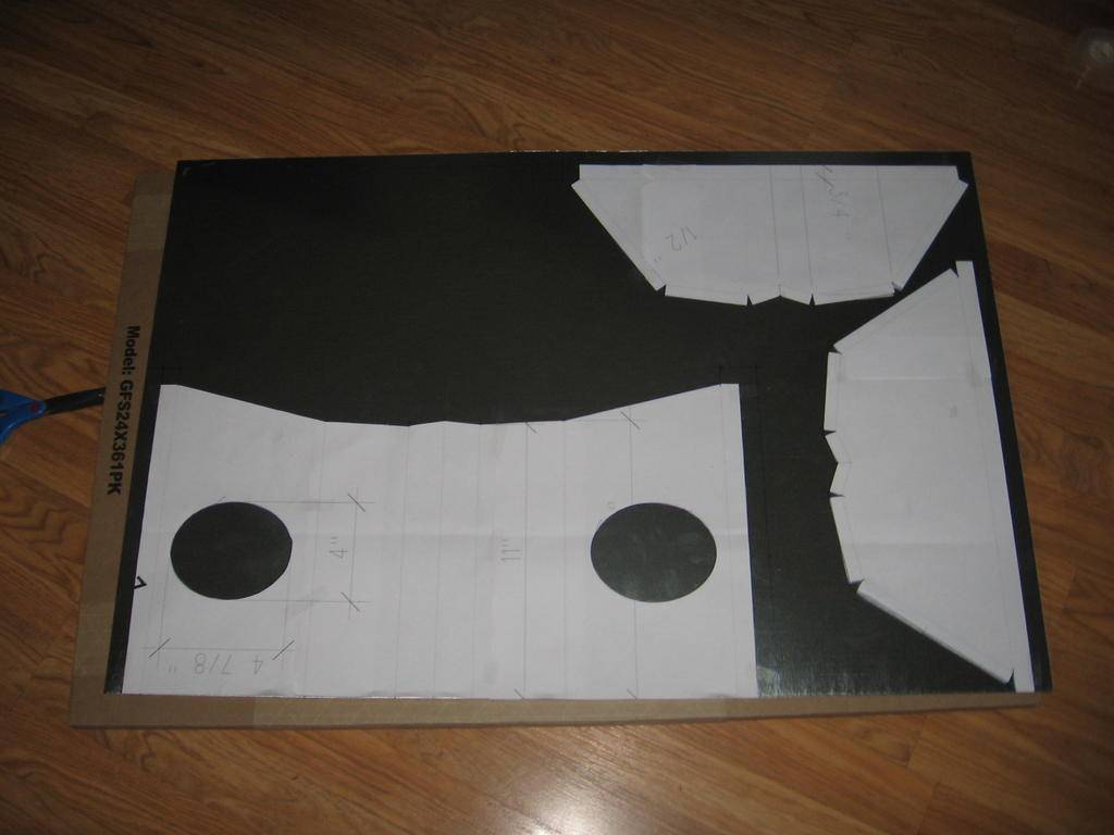 Using a permanent marker, transfer the shapes on to the sheet metal and cut the pieces. Draw all the fold lines and start bending. You will need something with a hard sharp edge to bend against. It’s best if there is some way to clamp while you are bending. I have a joiner/planer with a cast iron fence so that worked good but you will need to use your imagination. A piece of angle steel that you stand on will work. To make fold over hems you can bend to 90 degrees then finish by hand and flatten with by hammering against a flat surface.
Test fit while bending and when the pieces all fit good start connecting together. The first connection will be hardest but then it goes much easier. I tried soldering at first but this metal was too thin so I screwed the pieces together.
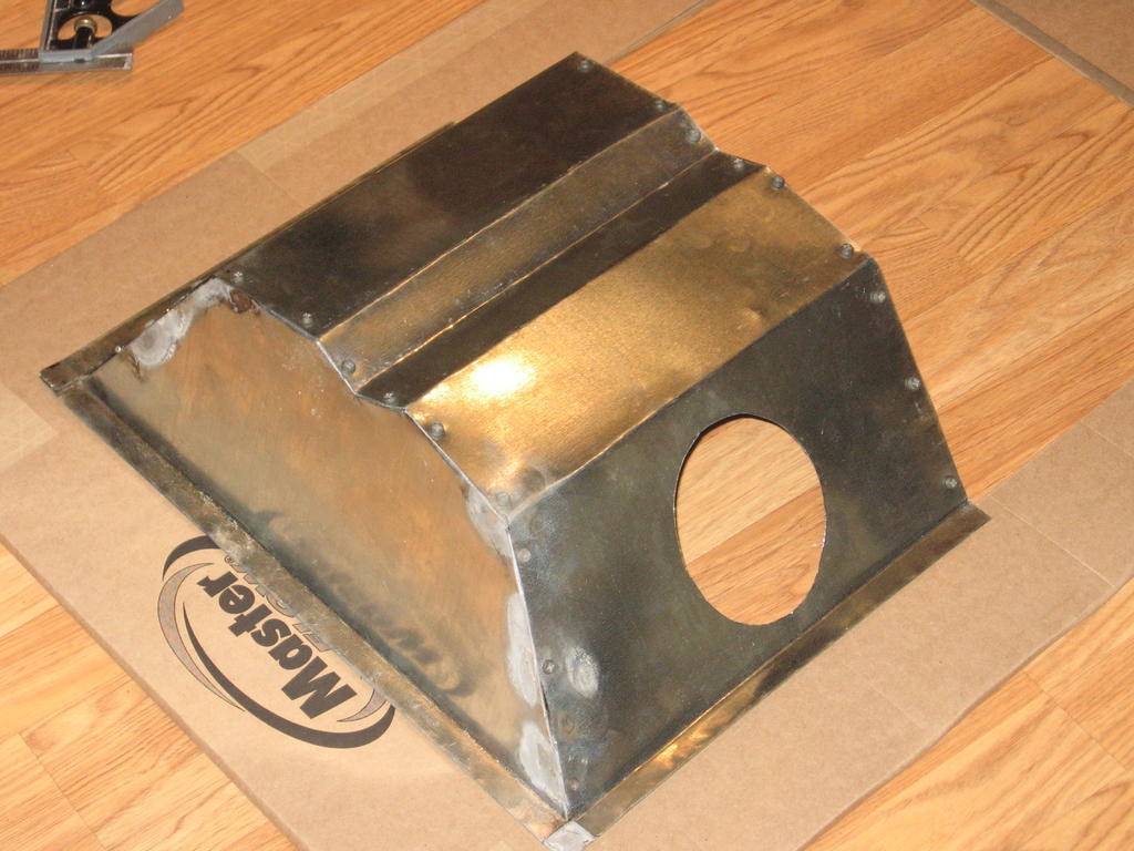 I didn’t like how that looked so I went back and changed out to pop rivets. Then I sealed up all the seams with foil tape to make the joints airtight.
 In my configuration I just barely have enough room to elbow out of the hood and hit the back wall. So I created a starter duct out of an elbow. To make a starter piece simply cut slits all the way around a duct fitting, then turn up every third one or so. If you have more room or want to use flex duct you could use a real starter flange or create one from duct parts. Set the starter piece in the hole and then bend the remaining tabs over to the inside until the fitting is secured in place.

 Seal the joint with short pieces of foil tape, inside and out, then repeat at fitting on other side.
Next is time to install the lamp socket and wiring. Originally I had envisioned putting a standard 1 ½” deep octagonal j-box on the back of the hood for the mogul socket mount. This worked fine for the generic bulb dimensions when I was designing the hood. As things progressed I came across a great deal for a digital ballast a EYE Hortilux bulb which is 9 ¾” long and would be too long to fit. I decided to use a ½” deep ceiling pan for a j-box on the outside of the hood and let it protrude through the back of the cabinet.

 I cut an opening in the back of the hood for the wires, ground the edges and lined the opening with duct tape. Then I drilled holes to match the j-box. To mount the socket I took a blank j-box cover plate (with a ½” knockout in the center) and drilled holes that matched the spacing for the mogul socket mounting screws. Then thread with wire through the j-box, cover plate and any lamp insulation pieces.
 Attach the wires to the appropriate terminals on the socket, then attach the socket to the cover plate with nuts. Feed the wire back through the j-box, tighten the loom clamp and install the cover plate/socket assembly.

The detail for the glass retainer is a screws with wing nuts through a 1/8 x ¾ flat bar glass retainer frame with foam tape on either side of the glass. The hood is designed with a ¾” perimeter flange and the 3/8” foam tape forms the glass bite so there is 3/8” left for the screws. There also has to be a spacer in this space that is the thickness of the glass and compressed foam, mine was 5/16“ thick. This is needed to prevent rotation as you tighten the screws. For the same price I found a ½ x ¾ x 1/16 aluminum angle that would be stronger and cap off the end nicely so I used it instead of the flat bar. I cut the angle to the lengths needed and laid out the spacing for the holes. Noticed later that the spacing is off so I must have been stoned, what can I say?
 I drilled the holes in the angle making sure they would be centered in the 3/8” space not filled with foam tape and glass. I clamped the angles in place as a template to drill matching holes in the hood flange perimeter. Or you could get the first hole drilled, put in a screw and nut to secure then drill the others. In any case it’s important for the holes to be matching. Mark the frame pieces so you know which ones go where.
Since in my design backs up against the back wall of the cabinet the back flange is turned inward. This means you can’t get to the screws like the other 3 sides so I glued them in place and used regular nuts instead of wing nuts. To install the glass I set the bar at the back loose and slip the glass between the gaskets, then set the front angle with a couple screw locations, and so on.
 The ducts came out a bit asymetrical so I set the hood in place to take measurements at fan box connections. I also added a cutout in the front for easy bulb changes.


I didn’t really keep track but this took me at least 25 hours and probably about $75 in materials. So if you have the $$ and the room you might want to consider a store-bought unit if you value your time. But for those times where it has to be a certain size to fit, the DIY approach was the answer to my problem.
I actually started out planning to build a simple bake-a-round cool tube for a new small cabinet. Then I realized the bulb really needed to be perpendicular to the long wall of my box for maximum efficiency. Didn’t have room to do that with the cool tube so the need for an air-cooled hood developed.
[edit see next post for drawing]
The next step was to create a flattened drawing for a cutting template. If you cut a section through a sheet metal fabrication in 2 directions there will always be a true dimension for each plane in one of those sections. Draw each plane in true size to cerate templates to cut the sheet metal shapes needed to fold up into the hood pieces. You will need to add tabs where the pieces join to make the attachment. I also added a length to fold at the edges to give a double thickness hemmed edge.
Test fit while bending and when the pieces all fit good start connecting together. The first connection will be hardest but then it goes much easier. I tried soldering at first but this metal was too thin so I screwed the pieces together.
Next is time to install the lamp socket and wiring. Originally I had envisioned putting a standard 1 ½” deep octagonal j-box on the back of the hood for the mogul socket mount. This worked fine for the generic bulb dimensions when I was designing the hood. As things progressed I came across a great deal for a digital ballast a EYE Hortilux bulb which is 9 ¾” long and would be too long to fit. I decided to use a ½” deep ceiling pan for a j-box on the outside of the hood and let it protrude through the back of the cabinet.
The detail for the glass retainer is a screws with wing nuts through a 1/8 x ¾ flat bar glass retainer frame with foam tape on either side of the glass. The hood is designed with a ¾” perimeter flange and the 3/8” foam tape forms the glass bite so there is 3/8” left for the screws. There also has to be a spacer in this space that is the thickness of the glass and compressed foam, mine was 5/16“ thick. This is needed to prevent rotation as you tighten the screws. For the same price I found a ½ x ¾ x 1/16 aluminum angle that would be stronger and cap off the end nicely so I used it instead of the flat bar. I cut the angle to the lengths needed and laid out the spacing for the holes. Noticed later that the spacing is off so I must have been stoned, what can I say?
Since in my design backs up against the back wall of the cabinet the back flange is turned inward. This means you can’t get to the screws like the other 3 sides so I glued them in place and used regular nuts instead of wing nuts. To install the glass I set the bar at the back loose and slip the glass between the gaskets, then set the front angle with a couple screw locations, and so on.
I didn’t really keep track but this took me at least 25 hours and probably about $75 in materials. So if you have the $$ and the room you might want to consider a store-bought unit if you value your time. But for those times where it has to be a certain size to fit, the DIY approach was the answer to my problem.

