
About me:
I have been reading the forums for some time now. I am new to growing. I enjoy improving efficiency in all things, and believe there is ALWAYS room to improve ANYTHING!
Scenario Background:
I have noticed the use of Cool Tubes for HID lighting. It seems that cooling HID lighting is an absolute must. I have been working on a couple small grow boxes for use with CFL's (Thanks Dr Green Genes for turning me onto CFL's - In my book they are the cats ass!). I quickly notticed that although CFL's run cool compared incandescent bulbs, they are by no means "COOL".
As I was building a PC grow box I had an idea... WHY NOT USE A COOL TUBE SYSTEM FOR CFL'S??? I decided to try the idea and the case was made into a prototype.
I KNOW a cool tube would greatly cool the CFL's, allowing plants to grow closer to the bulbs without burning and or allowing a larger margin of error. I HOPE this can also allow the case to run a cooler ambient temperature.
Sure CFL's are not that hot, but if you can alleviate the need to use AC on your grow, or you can get away with fewer or lower speed fans, ESPECIALLY FOR A STEALTH GROW why wouldn't you? If you are building a box from scratch this is likely less of a concern for you, but if you are using a PC case space is tight. Being able to get an inch closer to the lights could make a big difference.
So I built my version of a cool tube into my PC case. This is just a prototype, so I just took the easy (READ ugly, sloppy) method to make it work for now. I finally got around to running some tests this evening. I am still running these tests as I write. I will post some pictures first and use them to explain my test methodology.
***MEMO*** I should have pictures posted within the half hour along with some test results. About an hour later the full results from my first test run should be posted. ***
Design and Setup:
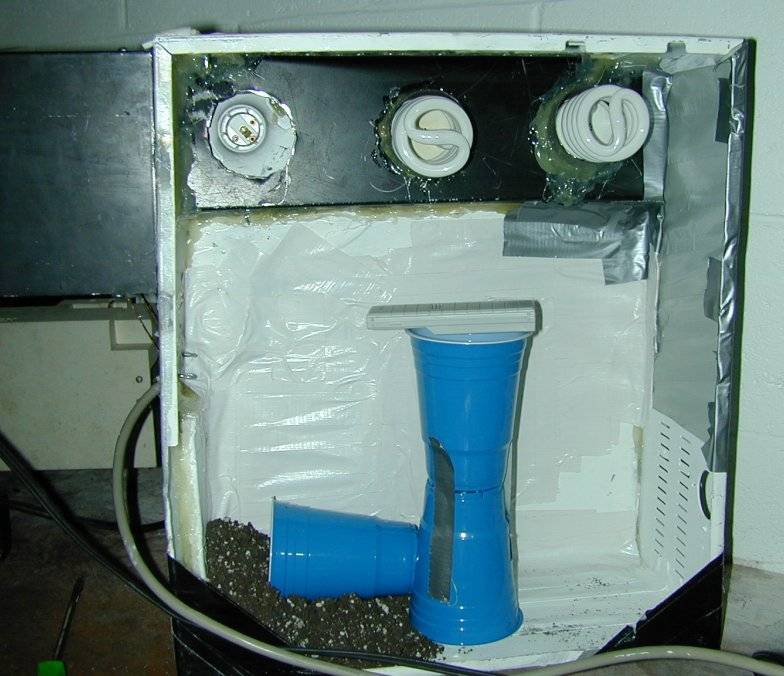
I used a piece of sheet metal to make the black portion (main body for the individual cool tube runners. It was quick and easy to shape.
I decided to have each tube cover a small amount of the bulb. the ballasts are running COLD, and I felt this would help direct the air flow over the bulbs to maximize cooling (while loosing a minimal amount of light).
Ideally the bulb would have an equal ring of air flow around the ballast, creating an even air flow across the bulb. Mine are crooked. But this is the prototype.
I decided to use the exhaust tubing to guide the air (instead of a glass tube across the length of the bulb) for 2 reasons.
1 - I did not have any glass tubing readily available.
2 - My partial tubes never need to be cleaned. More air flow = more dust. They can get a nice thick layer of dust and not affect light output") I like low maintenance stuff!
I like low maintenance stuff!
I used some automotive exhaust piping for the individual cool tube runners. Its readily available, reasonably priced and heat won't affect it.
The individual runners are secured to the black "tube" with an air tight seal of hot glue. The "back" side of the tubes are open within the black tube.
2 x 23w bulbs were used for the testing. Only 46 watts. I would expect a greater temperature differences if you are using between 100 - 200 watts of cfls.
This was the position of the air temp sensor for the first 2 tests. At which point I realized I should try to put the sensor in the very center of the case. The numbers would be more realistic (due to the location of the plants).
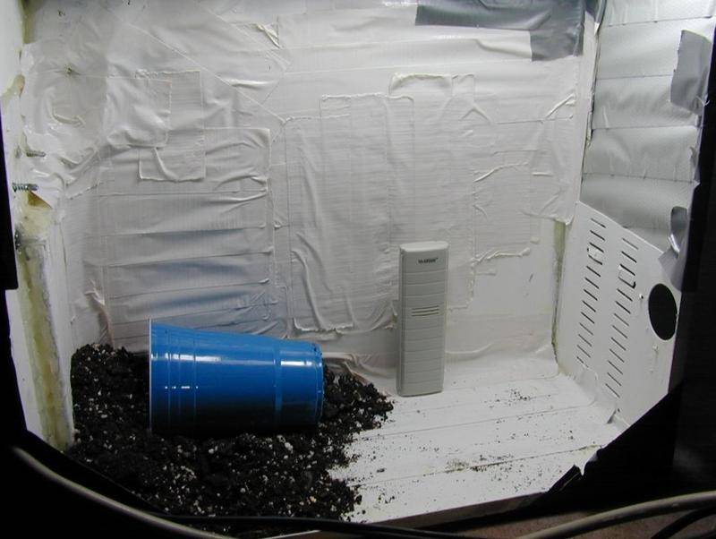
This was the position of the air temp sensor for tests 3 and 4. I feel it will provide information with greater accuracy. 2 tests were to make use of the cool tubes. For these (Tests 1 & 4) I covered the left socket hole with tape to seal it. Tests 2 & 3 were for comparison so I removed the tape to by-pass the cooling tube. Some air was still being pulled through the cool tubes, but it was a VERY small amount compared to the air drawn in the hole on the left.
The black box attached to the back of the case is a squirrel cage blower. The blower draws directly from the black rectangular tube. I do not know how many cfm it flows, but it is surely overkill for the small case. I found it in the workshop room when I moved into the house. Yeah free stuff kicks ass! Now that I think of it I will test the blower later to add that information.
TEST METHODOLOGY
* Air temps were measured with an indoor/outdoor combination thermometer (unit and remote sensor)
* Bulb temperatures were taken with a Mastercraft (Canadian Tire) brand infrared thermometer (remote temp gun)
* I used 2x 23w CFL bulbs in the case. I also used 1 of the same bulbs in a light socket in the test room, to compare. The CFL for comparison is hanging from the ceiling, wide open - no air flow, no reflector or shrouding.
* All bulb temperatures were a peak reading. I slowly ran the gun across all areas of each CFL to find a peak temperature (as I deemed this to be the most consitant method for my simplistic test).
* Each test was measured after roughly an hour. Test 1 occurred after 1 hour. Test 2 was conducted an hour after test 1 and so on.
* The left most bulb socket was never used with a bulb during testing. The "Middle" bulb shall be refered to as bulb 2. The "Right" bulb is bulb 3. The free air CFL is Bulb A.
--------------------------------------------------------------------------------------------------------
Test 1 - Cool Tube 1
- The temp sensor is on the bottom of the case (from 0 - 5" high).
- The bulbs and fan were fired up from a cold start and ran for an hour.
- The cool tubes were in use.
Ambient Air Temp 65.6f
Ambient Case Temp 66.0f
Bulb 2 116.0f
Bulb 3 119.8f
Bulb A 228.0f
--------------------------------------------------------------------------------------------------------
Test 2 - Bypass 1
- The temp sensor is on the bottom of the case (from 0 - 5" high).
- The bulbs remained on
- The tape was removed from the left hole as to bypass the cool tubes. I "believe" well over 97%+ of the air came through the hole on the left. I do know a very small amount
of air passed through the cool tubes.
Ambient Air Temp 65.8f
Ambient Case Temp 67.2f
Bulb 2 148.9f
Bulb 3 144.9f
Bulb A 222.5f
--------------------------------------------------------------------------------------------------------
Test 3 - Bypass #2
- The temp sensor is on raised to a "center" position.
- The bulbs remained on
- The tape was removed from the left hole as to bypass the cool tubes. I "believe" well over 97%+ of the air came through the hole on the left. I do know a very small amount
of air passed through the cool tubes.
Ambient Air Temp 65.8f
Ambient Case Temp 69.4f
Bulb 2 147.6f
Bulb 3 143.3f
Bulb A 227.0f
--------------------------------------------------------------------------------------------------------
Test 4 - Cool Tube #2
- The temp sensor is on raised to a "center" position.
- The bulbs remained on
- The cool tubes were in use.
Ambient Air Temp 65.8f
Ambient Case Temp 68.5f
Bulb 2 #121.6f
Bulb 3 #118.4f
Bulb A #225.0f
AS I expected the cool tubes "greatly" cooled the CFL bulbs. The difference in bulb temperature is indeed noticeable. In this case it was to the tune of about 21%.
The ambient air temperature was affect but only to a small extent, about 1.5%.
2 things to keep in mind - my air flow is likely VERY high for such a small cabinet. Also the wattage during the test was very low. I look forward to retrying this test using 2 high wattage bulbs sometime soon. I also look forward to figuring out the flow rate of my fan so I we can better interrupt the test results.
I have been reading the forums for some time now. I am new to growing. I enjoy improving efficiency in all things, and believe there is ALWAYS room to improve ANYTHING!
Scenario Background:
I have noticed the use of Cool Tubes for HID lighting. It seems that cooling HID lighting is an absolute must. I have been working on a couple small grow boxes for use with CFL's (Thanks Dr Green Genes for turning me onto CFL's - In my book they are the cats ass!). I quickly notticed that although CFL's run cool compared incandescent bulbs, they are by no means "COOL".
As I was building a PC grow box I had an idea... WHY NOT USE A COOL TUBE SYSTEM FOR CFL'S??? I decided to try the idea and the case was made into a prototype.
I KNOW a cool tube would greatly cool the CFL's, allowing plants to grow closer to the bulbs without burning and or allowing a larger margin of error. I HOPE this can also allow the case to run a cooler ambient temperature.
Sure CFL's are not that hot, but if you can alleviate the need to use AC on your grow, or you can get away with fewer or lower speed fans, ESPECIALLY FOR A STEALTH GROW why wouldn't you? If you are building a box from scratch this is likely less of a concern for you, but if you are using a PC case space is tight. Being able to get an inch closer to the lights could make a big difference.
So I built my version of a cool tube into my PC case. This is just a prototype, so I just took the easy (READ ugly, sloppy) method to make it work for now. I finally got around to running some tests this evening. I am still running these tests as I write. I will post some pictures first and use them to explain my test methodology.
***MEMO*** I should have pictures posted within the half hour along with some test results. About an hour later the full results from my first test run should be posted. ***
Design and Setup:
I used a piece of sheet metal to make the black portion (main body for the individual cool tube runners. It was quick and easy to shape.
I decided to have each tube cover a small amount of the bulb. the ballasts are running COLD, and I felt this would help direct the air flow over the bulbs to maximize cooling (while loosing a minimal amount of light).
Ideally the bulb would have an equal ring of air flow around the ballast, creating an even air flow across the bulb. Mine are crooked. But this is the prototype.
I decided to use the exhaust tubing to guide the air (instead of a glass tube across the length of the bulb) for 2 reasons.
1 - I did not have any glass tubing readily available.
2 - My partial tubes never need to be cleaned. More air flow = more dust. They can get a nice thick layer of dust and not affect light output
I like low maintenance stuff!I used some automotive exhaust piping for the individual cool tube runners. Its readily available, reasonably priced and heat won't affect it.
The individual runners are secured to the black "tube" with an air tight seal of hot glue. The "back" side of the tubes are open within the black tube.
2 x 23w bulbs were used for the testing. Only 46 watts. I would expect a greater temperature differences if you are using between 100 - 200 watts of cfls.
This was the position of the air temp sensor for the first 2 tests. At which point I realized I should try to put the sensor in the very center of the case. The numbers would be more realistic (due to the location of the plants).
This was the position of the air temp sensor for tests 3 and 4. I feel it will provide information with greater accuracy. 2 tests were to make use of the cool tubes. For these (Tests 1 & 4) I covered the left socket hole with tape to seal it. Tests 2 & 3 were for comparison so I removed the tape to by-pass the cooling tube. Some air was still being pulled through the cool tubes, but it was a VERY small amount compared to the air drawn in the hole on the left.
The black box attached to the back of the case is a squirrel cage blower. The blower draws directly from the black rectangular tube. I do not know how many cfm it flows, but it is surely overkill for the small case. I found it in the workshop room when I moved into the house. Yeah free stuff kicks ass! Now that I think of it I will test the blower later to add that information.
TEST METHODOLOGY
* Air temps were measured with an indoor/outdoor combination thermometer (unit and remote sensor)
* Bulb temperatures were taken with a Mastercraft (Canadian Tire) brand infrared thermometer (remote temp gun)
* I used 2x 23w CFL bulbs in the case. I also used 1 of the same bulbs in a light socket in the test room, to compare. The CFL for comparison is hanging from the ceiling, wide open - no air flow, no reflector or shrouding.
* All bulb temperatures were a peak reading. I slowly ran the gun across all areas of each CFL to find a peak temperature (as I deemed this to be the most consitant method for my simplistic test).
* Each test was measured after roughly an hour. Test 1 occurred after 1 hour. Test 2 was conducted an hour after test 1 and so on.
* The left most bulb socket was never used with a bulb during testing. The "Middle" bulb shall be refered to as bulb 2. The "Right" bulb is bulb 3. The free air CFL is Bulb A.
--------------------------------------------------------------------------------------------------------
Test 1 - Cool Tube 1
- The temp sensor is on the bottom of the case (from 0 - 5" high).
- The bulbs and fan were fired up from a cold start and ran for an hour.
- The cool tubes were in use.
Ambient Air Temp 65.6f
Ambient Case Temp 66.0f
Bulb 2 116.0f
Bulb 3 119.8f
Bulb A 228.0f
--------------------------------------------------------------------------------------------------------
Test 2 - Bypass 1
- The temp sensor is on the bottom of the case (from 0 - 5" high).
- The bulbs remained on
- The tape was removed from the left hole as to bypass the cool tubes. I "believe" well over 97%+ of the air came through the hole on the left. I do know a very small amount
of air passed through the cool tubes.
Ambient Air Temp 65.8f
Ambient Case Temp 67.2f
Bulb 2 148.9f
Bulb 3 144.9f
Bulb A 222.5f
--------------------------------------------------------------------------------------------------------
Test 3 - Bypass #2
- The temp sensor is on raised to a "center" position.
- The bulbs remained on
- The tape was removed from the left hole as to bypass the cool tubes. I "believe" well over 97%+ of the air came through the hole on the left. I do know a very small amount
of air passed through the cool tubes.
Ambient Air Temp 65.8f
Ambient Case Temp 69.4f
Bulb 2 147.6f
Bulb 3 143.3f
Bulb A 227.0f
--------------------------------------------------------------------------------------------------------
Test 4 - Cool Tube #2
- The temp sensor is on raised to a "center" position.
- The bulbs remained on
- The cool tubes were in use.
Ambient Air Temp 65.8f
Ambient Case Temp 68.5f
Bulb 2 #121.6f
Bulb 3 #118.4f
Bulb A #225.0f
AS I expected the cool tubes "greatly" cooled the CFL bulbs. The difference in bulb temperature is indeed noticeable. In this case it was to the tune of about 21%.
The ambient air temperature was affect but only to a small extent, about 1.5%.
2 things to keep in mind - my air flow is likely VERY high for such a small cabinet. Also the wattage during the test was very low. I look forward to retrying this test using 2 high wattage bulbs sometime soon. I also look forward to figuring out the flow rate of my fan so I we can better interrupt the test results.
Last edited:


